Toyota Sienna Service Manual: Precaution
1. HANDLING PRECAUTION FOR CRUISE CONTROL SYSTEM
- Turn the cruise control main switch off when not using the cruise control system.
- Be careful as the vehicle speed increases when driving downhill with the cruise control system on.
- The + (ACCEL)/RES (RESUME) operation changes according to the cruise control system status. When the cruise control system is operating, the + (ACCEL) function operates. When the cruise control system is not operating, the RES (RESUME) function operates.
- If the CRUISE main indicator light blinks while the cruise control system is operating, turn the cruise control main switch off to reset the cruise control system. After the reset, if the cruise control main switch cannot be turned on, or the cruise control system is canceled immediately after turning the cruise control main switch on, the system may have a malfunction.
- Do not use the cruise control system where the road conditions are as follows:
- Heavy traffic
- Steep decline
- Roads with sharp turns
- Icy or snowy roads
- Slippery roads
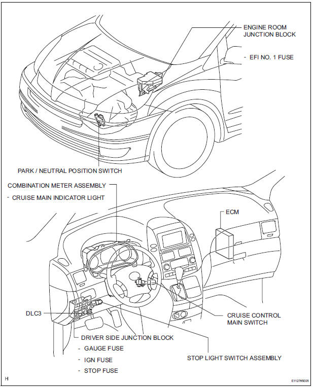
PARTS LOCATION
SYSTEM DIAGRAM
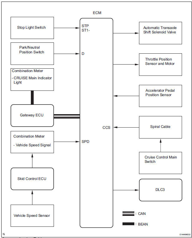
Communication Table:


 System description
1. CRUISE CONTROL SYSTEM
This system is controlled by the ECM, and is activated by
the throttle position sensor and motor. The ECM controls
the following functions: ON-OFF, - (COAST)/SET, +
(ACCEL ...
Other materials:
Removal
1. DISCONNECT CABLE FROM NEGATIVE BATTERY
TERMINAL
CAUTION:
Wait for 90 seconds after disconnecting the cable to prevent the airbag working
2. REMOVE FRONT SEAT ASSEMBLY
HINT:
Refer to the instructions for removal of the front seat assembly (for
flat type).
Refer to the ins ...
Antenna Coil Open / Short
DTC B2784 Antenna Coil Open / Short
DESCRIPTION
The transponder key coil is built into the transponder key amplifier and
receives a key code signal from
the transponder chip in the key. This signal is amplified by the amplifier, and
output to the transponder key
ECU.
DTC No.
...
Wiper and washer system
PRECAUTION
1. PRECAUTION OF WASHER NOZZLE ADJUSTMENT
Do not clean or adjust the washer nozzle with a
safety pin, etc. because;
the washer nozzle tip is made of resin and could
be damaged.
adjustment is not necessary because the
washer nozzle is a spray type.
...
