Toyota Sienna Service Manual: Precaution
1. Check that the battery cables are connected to the correct terminals.
2. Disconnect the battery cables when the battery is given a quick charge.
3. Do not perform tests with a high voltage insulation resistance tester.
4. Never disconnect the battery cables while the engine is running.
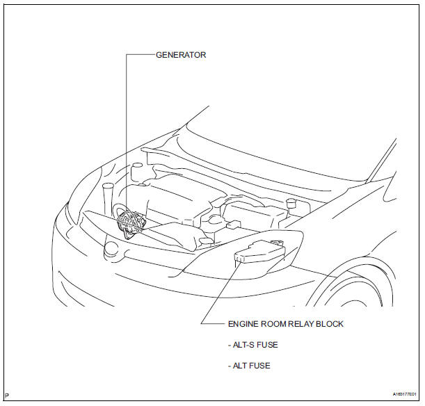
5. Check that the charging cable nut is tightened on terminal b of the generator and the engine room r/b.
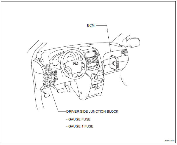
Parts location
SYSTEM DIAGRAM

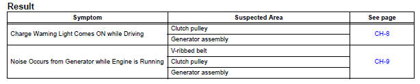
PROBLEM SYMPTOMS TABLE
 Charging system
...
 On-vehicle inspection
1. Check battery electrolyte level
(a) Check the electrolyte level.
(1) If the electrolyte level is low, replace the battery
(or add distilled water) and check the charging
system.
2. CHECK BAT ...
Other materials:
Low Battery Positive Voltage
DTC C1241/41 Low Battery Positive Voltage
DESCRIPTION
WIRING DIAGRAM
INSPECTION PROCEDURE
1 INSPECT ECU-IG FUSE
(a) Remove the ECU-IG fuse from the driver side J/B.
(b) Check continuity of the ECU-IG fuse.
Standard resistance
2 CHECK BATTERY
(a) Check the positive battery volt ...
Fail-safe chart
1. FAIL-SAFE
This function minimizes the loss of the ECT functions
when any malfunction occurs in a sensor or solenoid.
(a) ATF (Automatic Transmission Fluid) temperature
sensor:
When the ATF temperature sensor has a
malfunction, 5th upshift is prohibited.
(b) Counter gear speed sensor NC ...
Television display
COMPONENTS
Removal
1. REMOVE TELEVISION BASE
Release the 4 clips and remove the television base.
2. REMOVE TELEVISION DISPLAY ASSEMBLY
Disconnect the connector and remove the 4 bolts
and the television display assembly.
Installation
1. INSTALL TELEVISION DISP ...
