Toyota Sienna Service Manual: Pressure Control Solenoid "C" Electrical (Shift Solenoid Valve SL3)
DESCRIPTION
Shifting from 1st to 5th is performed in combination with "ON" and "OFF"
operation of the shift solenoid
valves SL1, SL2, SL3, S4 and SR which are controlled by the ECM. If an open or
short circuit occurs in
either of the shift solenoid valves, the ECM controls the remaining normal shift
solenoid valves to allow
the vehicle to be operated smoothly (Fail safe function).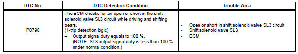
MONITOR DESCRIPTION
The ECM commands gear shifts by turning the shift solenoid valves "ON/OFF". When there is an open or short circuit in any shift solenoid valve circuit, the ECM detects the problem and illuminates the MIL and stores the DTC. And the ECM performs the fail-safe function and turns the other normal shift solenoid valves "ON/OFF" (In case of an open or short circuit, the ECM stops sending current to the circuit.) (See page AX-30).
MONITOR STRATEGY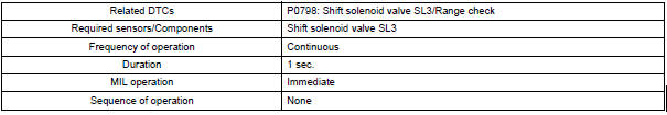
TYPICAL ENABLING CONDITIONS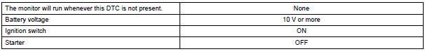
TYPICAL MALFUNCTION THRESHOLDS
COMPONENT OPERATING RANGE

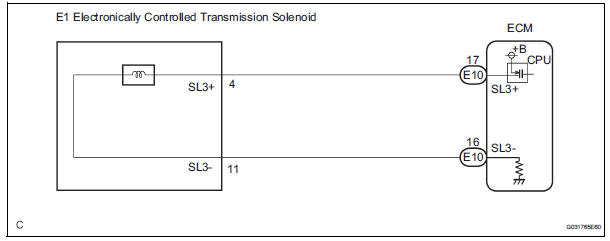
WIRING DIAGRAM
INSPECTION PROCEDURE
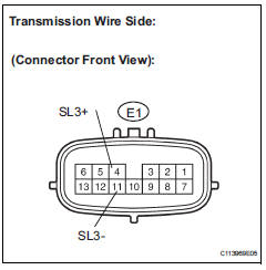
(a) Disconnect the transmission wire connector from the transaxle.
(b) Measure the resistance according to the value(s) in the table below.
Standard resistance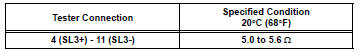
(c) Measure the resistance according to the value(s) in the table below.
Standard resistance (Check for short)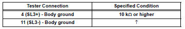

2 CHECK HARNESS AND CONNECTOR (TRANSMISSION WIRE - ECM)
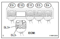
(a) Connect the transmission wire connector to the transaxle.
(b) Disconnect the connector from the ECM.
(c) Measure the resistance according to the value(s) in the table below.
Standard resistance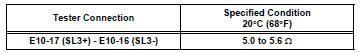
(d) Measure the resistance according to the value(s) in the table below.
Standard resistance (Check for short)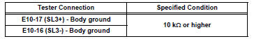

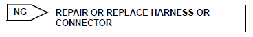
REPLACE ECM
3 INSPECT SHIFT SOLENOID VALVE SL3
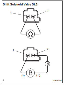
(a) Remove the shift solenoid valve SL3.
(b) Measure the resistance according to the value(s) in the table below.
Standard resistance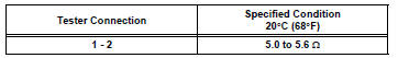
(c) Connect the positive (+) lead with a 21 W bulb to terminal 2 and the negative (-) lead to terminal 1 of the solenoid valve connector, then check the movement of the valve.
OK: The solenoid makes an operating sound.

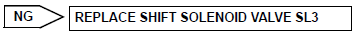
REPAIR OR REPLACE TRANSMISSION WIRE
 Pressure Control Solenoid "C" Performance (Shift
Solenoid Valve SL3)
Pressure Control Solenoid "C" Performance (Shift
Solenoid Valve SL3)
SYSTEM DESCRIPTION
The ECM uses signals from the vehicle speed sensor to detect the actual gear
position (1st, 2nd, 3rd, 4th
or 5th gear).
Then the ECM compares the actual gear with the shift s ...
 Shift Solenoid "D" Control Circuit
DESCRIPTION
Shifting from 1st to 5th is performed in combination with "ON" and "OFF"
operation of the shift solenoid
valves SL1, SL2, SL3, S4 and SR which are controlled by ...
Other materials:
Reassembly
1. INSTALL FUEL PRESSURE REGULATOR ASSEMBLY
(a) Apply a light coat of gasoline or spindle oil to the 2
new O-rings, and install it to the fuel pressure
regulator.
(b) Apply a light coat of gasoline or spindle oil to the 2
O-rings again, and install the fuel pressure regulator
to the No. ...
Detailed Bluetooth®
system settings
You can confirm and change the detailed Bluetooth® settings.
How to check and change detailed Bluetooth® settings
Display the “Bluetooth* Setup” screen.
Select “System Settings”.
The following screen is displayed:
Bluetooth* Power on/off
You can change Bluetooth*
fu ...
Air conditioning controls
Adjusting the temperature setting
Press “” on the “TEMP” button to
increase the temperature and “”
to decrease the temperature.
Adjusting the fan speed
Press “” on
to increase the fan speed and “”
to decrease
the fan speed.
Press the “OFF” button to turn the ...
