Toyota Sienna Service Manual: Pressure Control Solenoid "D" Electrical (Shift Solenoid Valve SLT)
DESCRIPTION
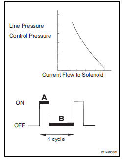
The linear solenoid valve (SLT) controls the transmission line pressure for smooth transmission operation based on signals from the throttle position sensor and the vehicle speed sensor. The ECM adjusts the duty cycle of the SLT solenoid valve to control hydraulic line pressure coming from the primary regulator valve. Appropriate line pressure assures smooth shifting with varying engine outputs.
(*): Duty Ratio The duty ratio is the ratio of the period of continuity in one cycle.
For example, if A is the period of continuity in one cycle, and B is the period
of non-continuity, then
Duty Ratio = A/(A + B) x 100(%)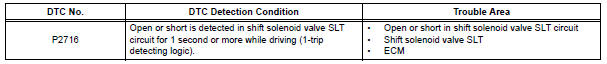
MONITOR DESCRIPTION
When an open or short in the linear solenoid valve (SLT) circuit is detected, the ECM interprets this as a fault. The ECM will turn on the MIL and store the DTC.
MONITOR STRATEGY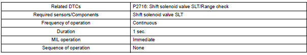
TYPICAL ENABLING CONDITIONS
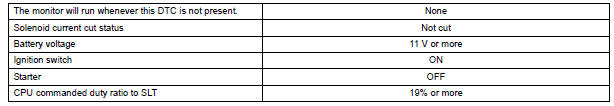
TYPICAL MALFUNCTION THRESHOLDS

COMPONENT OPERATING RANGE

WIRING DIAGRAM

INSPECTION PROCEDURE
1 INSPECT TRANSMISSION WIRE (SLT)
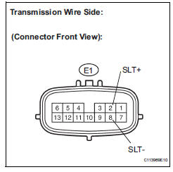
(a) Disconnect the transmission wire connector from the transaxle.
(b) Measure the resistance according to the value(s) in the table below.
Standard resistance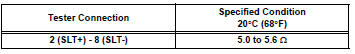
(c) Measure the resistance according to the value(s) in the table below.
Standard resistance (Check for short)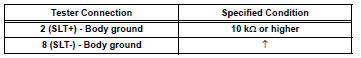

2 CHECK HARNESS AND CONNECTOR (TRANSMISSION WIRE - ECM)
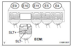
(a) Connect the transmission wire connector to the transaxle.
(b) Disconnect the ECM connector.
(c) Measure the resistance according to the value(s) in the table below.
Standard resistance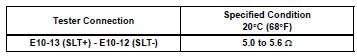
(d) Measure the resistance according to the value(s) in the table below.
Standard resistance (Check for short)


REPLACE ECM
3 INSPECT SHIFT SOLENOID VALVE SLT
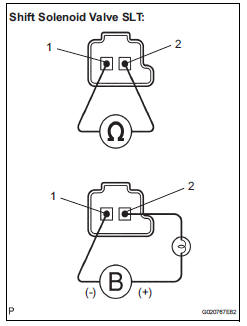
(a) Remove the shift solenoid valve (SLT).
(b) Measure the resistance according to the value(s) in the table below.
Standard resistance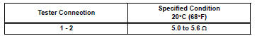
(c) Connect the positive (+) lead with a 21 W bulb to terminal 2 and the negative (-) lead to terminal 1 of the solenoid valve connector, then check the movement of the valve.
OK: The solenoid makes an operating sound.

REPAIR OR REPLACE TRANSMISSION WIRE
 Pressure Control Solenoid "D" Performance (Shift
Solenoid Valve SLT)
Pressure Control Solenoid "D" Performance (Shift
Solenoid Valve SLT)
SYSTEM DESCRIPTION
The linear solenoid valve (SLT) controls the transmission line pressure for
smooth transmission operation
based on signals from the throttle position sensor and the vehicle spee ...
 Torque Converter Clutch Solenoid Circuit
DESCRIPTION
The shift solenoid valve DSL is turned "ON" and "OFF" by signals from the ECM
in order to control the
hydraulic pressure operation, the lock-up relay valve, whi ...
Other materials:
Installation
1. INSTALL BRAKE VACUUM CHECK VALVE
ASSEMBLY
(a) Install the brake vacuum check valve assembly and
check valve grommet to the brake booster
assembly.
2. INSTALL BRAKE BOOSTER GASKET
(a) Install a new brake booster gasket to the brake
booster with master cylinder.
3. INSTALL BRAKE MASTER CYLI ...
Zero Point Calibration of Yaw Rate Sensor Undone
DESCRIPTION
The skid control ECU receives signals from the yaw rate sensor via CAN
communication system.
Yaw rate sensor has the built-in deceleration sensor.
If there is trouble in the bus lines between the yaw rate and deceleration
sensor and CAN communication
system, the DTC U0123 ...
Positioning a floor jack
When using a floor jack, follow the instructions in the manual
provided with the jack and perform the operation safely.
When raising your vehicle with a floor jack, position the jack correctly.
Improper placement may damage your vehicle or cause
injury.
Front
Rear
2WD ...
