Toyota Sienna Service Manual: Pressure Control Solenoid "D" Performance (Shift Solenoid Valve SLT)
SYSTEM DESCRIPTION
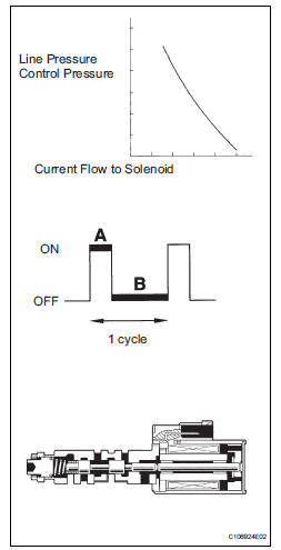
The linear solenoid valve (SLT) controls the transmission line pressure for smooth transmission operation based on signals from the throttle position sensor and the vehicle speed sensor. The ECM adjusts the duty ratio (*) of the SLT solenoid valve to control hydraulic line pressure coming from the primary regulator valve. Appropriate line pressure assures smooth shifting with varying engine outputs.
(*): Duty Ratio
The duty ratio is the ratio of the period of continuity in one cycle. For
example, if A is the period of
continuity in one cycle, and B is the period of non-continuity, then
Duty Ratio=A/(A+B) x 100(%)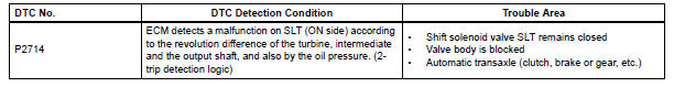
MONITOR DESCRIPTION
In any forward position, when the difference between the revolutions of the turbine, Intermediate and output shaft exceeds the specified value (varies with Intermediate, output speed) determined by the ECM, the ECM illuminates the MIL and store the DTC.
When shift solenoid valve SLT remains on, the oil pressure goes down and the clutch engagement force decreases.
| NOTICE: If you continue driving under these conditions, the clutch will burn out and the vehicle will no longer be drivable. |
MONITOR STRATEGY
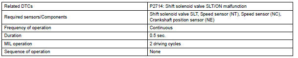
TYPICAL ENABLING CONDITIONS
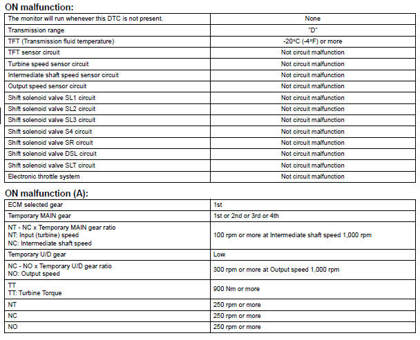
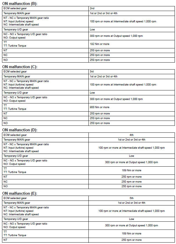

TYPICAL MALFUNCTION THRESHOLDS
[ON malfunction] Detection condition: Total accumulated time of ON malfunctions (a), (b), (c), (d) and (e) is 0.5 second or more
INSPECTION PROCEDURE
1 CHECK OTHER DTCS OUT PUT (IN ADDITION TO DTC P2714)
(a) Connect the OBD II scan tool or intelligent tester together with the CAN VIM (controller area network vehicle interface module) to the DLC3.
(b) Turn the ignition switch to the ON position and turn the OBD II scan tool or the intelligent tester main switch ON.
(c) When you use intelligent tester: Select the item "DIAGNOSIS / ENHANCED OBD II / DTC INFO / CURRENT CODES" (d) Read the DTCs using the OBD II scan tool or the intelligent tester.
Result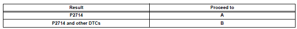
HINT: If any other codes besides "P2714" are output, perform the troubleshooting for those DTCs first.

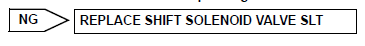
2 INSPECT SHIFT SOLENOID VALVE SLT
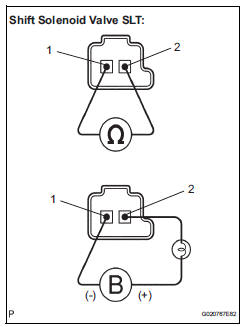
(a) Remove the shift solenoid valve SLT.
(b) Measure the resistance according to the value(s) in the table below.
Standard resistance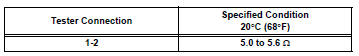
(c) Connect the positive (+) lead with a 21 W bulb to terminal 2 and the negative (-) lead to terminal 1 of the solenoid valve connector, then check the movement of the valve.
OK: The solenoid makes an operating sound.

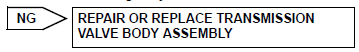
3 INSPECT TRANSMISSION VALVE BODY ASSEMBLY
OK: There are no foreign objects on each valve.

4 INSPECT TORQUE CONVERTER CLUTCH ASSEMBLY
OK: The torque converter clutch operates normally.

REPAIR OR REPLACE AUTOMATIC TRANSAXLE ASSEMBLY
 Shift Solenoid "E" Control Circuit
DESCRIPTION
Shifting from 1st to 5th is performed in combination with "ON" and "OFF"
operation of the shift solenoid
valves SL1, SL2, SL3, S4 and SR which are controlled by ...
 Pressure Control Solenoid "D" Electrical (Shift
Solenoid Valve SLT)
Pressure Control Solenoid "D" Electrical (Shift
Solenoid Valve SLT)
DESCRIPTION
The linear solenoid valve (SLT) controls the transmission line pressure for
smooth transmission operation
based on signals from the throttle position sensor and the vehicle speed senso ...
Other materials:
Short in Side Squib LH Circuit
DTC B0115/47 Short in Side Squib LH Circuit
DESCRIPTION
The side squib LH circuit consists of the center airbag sensor assembly and
the front seat side airbag
assembly LH.
This circuit instructs the SRS to deploy when deployment conditions are met.
DTC B0115/47 is recorded when a short ci ...
System check
HINT:
Performing a SYSTEM CHECK enables the system,
which consists of the multiple actuators, to be operated
without removing any parts. In addition, it can show
whether or not any DTCs are set, and can detect
potential malfunctions in the system. The SYSTEM
CHECK can be performed with an inte ...
Power Seat ECU Communication Stop
DTC B1272 Power Seat ECU Communication Stop
DESCRIPTION
This DTC is detected when communication between the seat position control ECU
and the multiplex
network gateway ECU stops for more than 10 seconds.
DTC No.
DTC Detection Condition
Trouble Area
B1272
...
