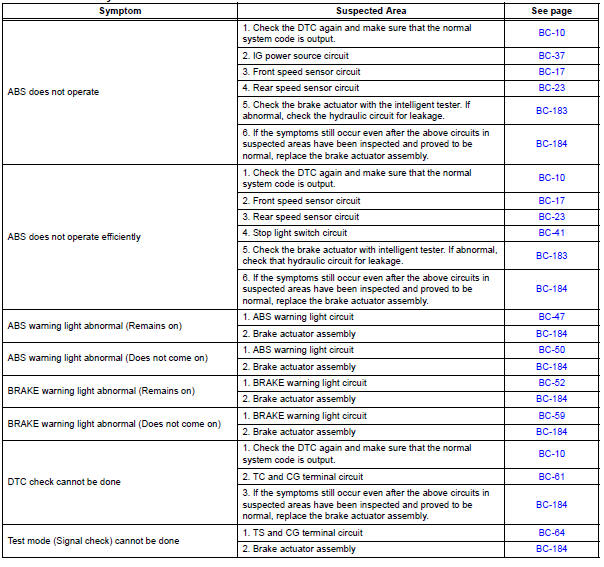
Toyota Sienna Service Manual: Problem symptoms table
If there are no DTCs output but the problem still occurs, check the circuits for each problem symptom in the order given in the table below and proceed to the relevant troubleshooting page.
NOTICE: When replacing the brake actuator assembly, sensor, etc., turn the ignition switch off.
HINT: Inspect the fuse and relay before investigating the suspected areas as shown in the table below. Inspect each malfunction circuit in numerical order for the corresponding symptom.
Anti-lock brake system:
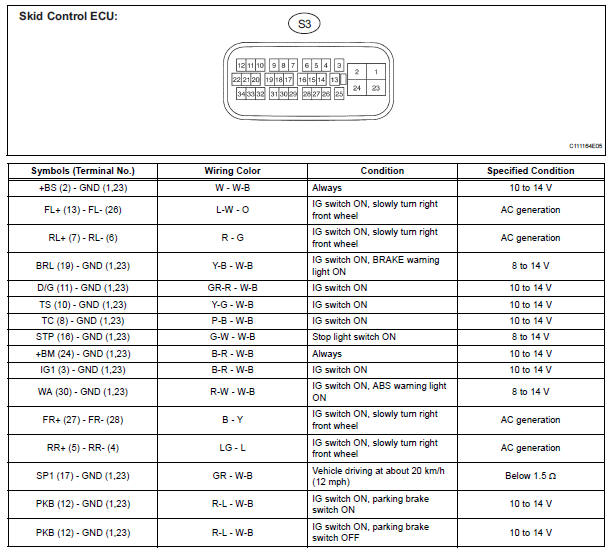
Terminals of ecu
 Test mode procedure
1. SPEED SENSOR SIGNAL CHECK (WHEN USING SST CHECK WIRE):
HINT:
If the ignition switch is turned from the ON to the ACC
or LOCK position during Test Mode, the DTCs of the
signal check functio ...
 Diagnosis system
1. DESCRIPTION
(a) Release the parking brake pedal.
(b) Check the warning lights.
When ignition switch is turned ON, check that the
ABS warning light and brake warning light come on
for 3 ...
Other materials:
Personal/interior
lights
Front
Turns the light on/off
Rear
Turns the light on/off
When the personal/interior light main switch is in the off position, the
rear personal lights will not turn on even if the switch is on.
Type A
Type B
...
Front Airbag Sensor LH Circuit Malfunction
DTC B1149/37 Front Airbag Sensor LH Circuit Malfunction
DESCRIPTION
The front airbag sensor LH circuit consists of the center airbag sensor
assembly and front airbag sensor
LH.
If the center airbag sensor assembly receives signals from the front airbag
sensor LH, it judges whether or
not ...
Disassembly
1. INSPECT UNDERDRIVE PLANETARY GEAR
PRELOAD
HINT:
(See page AX-260)
2. REMOVE FRONT PLANETARY GEAR NUT
(a) Using SST, loosen the staked part of the lock nut.
SST 09930-00010 (09931-00010, 09931-00020),
09387-00050
(b) Place the underdrive planetary gear in a soft jaw
vise.
NOTIC ...
