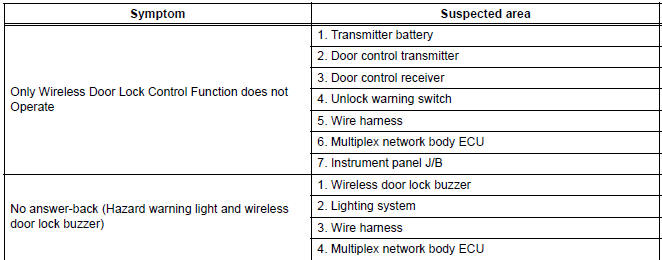
Toyota Sienna Service Manual: Problem symptoms table
HINT: Inspect the fuse and relay before investigating the suspected areas shown in the table below.
WIRELESS DOOR LOCK CONTROL SYSTEM:
 Customize parameters
HINT:
The following items can be customized.
NOTICE:
When the customer requests a change in a function,
first make sure that customization of the function(s) is
possible.
Be su ...
 Terminals of ECU
1. INSTRUMENT PANEL JUNCTION BLOCK
(MULTIPLEX NETWORK BODY ECU)
Disconnect the B6, B7 and B9 ECU connectors.
Disconnect the 1A, 1C, 1K, 1L and 1P J/B
connectors.
Check the vol ...
Other materials:
Installation
1. INSTALL REAR SEAT 3 POINT TYPE BELT
ASSEMBLY (for 8-Passenger)
HINT: Refer to the instructions for reassembly of the rear
No. 1 seat assembly (for center seat).
Install the rear seat 3 point type belt assembly with
the bolt.
Torque: 42 N*m (430 kgf*cm, 31 ft.*lbf)
2. INSTALL ...
Customize parameters
HINT:
The following items can be customized.
NOTICE:
After confirming whether the items requested by the
customer are applicable or not for customization,
perform the customize operation.
Be sure to record the current settings before
customizing.
When troubleshooting, make sure that ...
Reassembly
1. INSTALL SEAT POSITION AIRBAG SENSOR (for Driver Seat)
2. INSTALL FRONT SEAT CUSHION SHIELD LOWER LH
Install the front seat cushion shield lower LH with
the screw.
3. INSTALL FRONT SEAT CUSHION SHIELD LOWER
RH
HINT:
Use the same procedures for the RH side and LH side.
4. INSTAL ...
