Toyota Sienna Service Manual: Problem symptoms table
ENTIRE SYSTEM
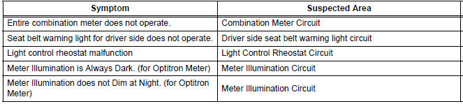
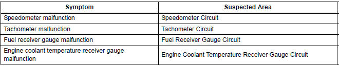
METER GAUGES
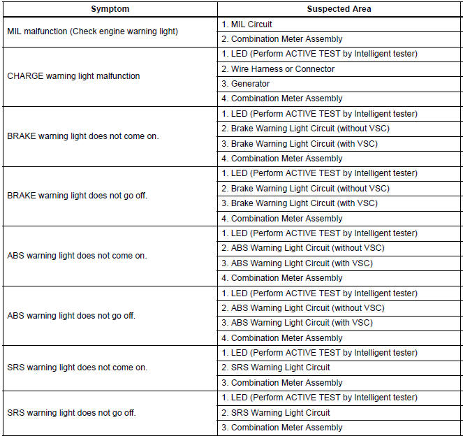
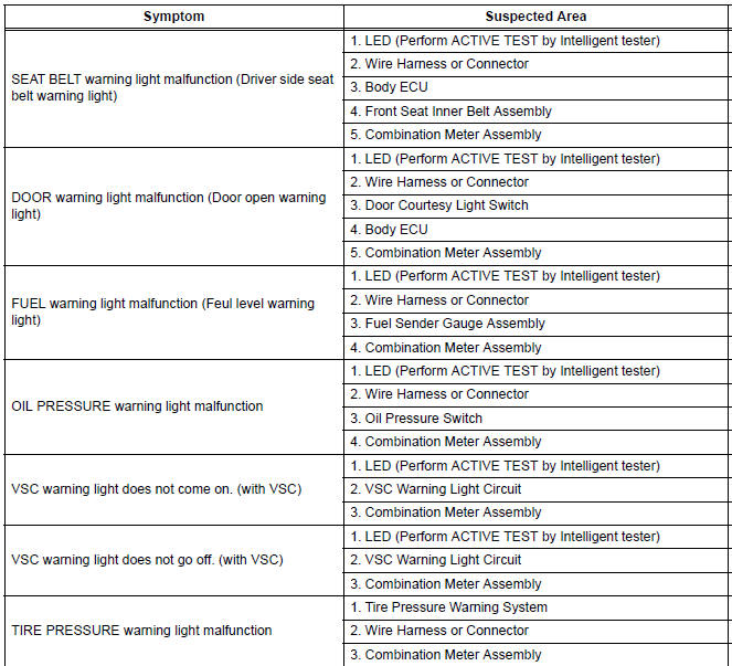
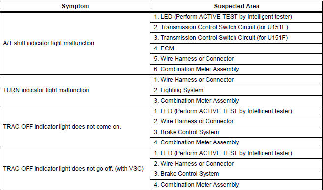
WARNING LIGHTS
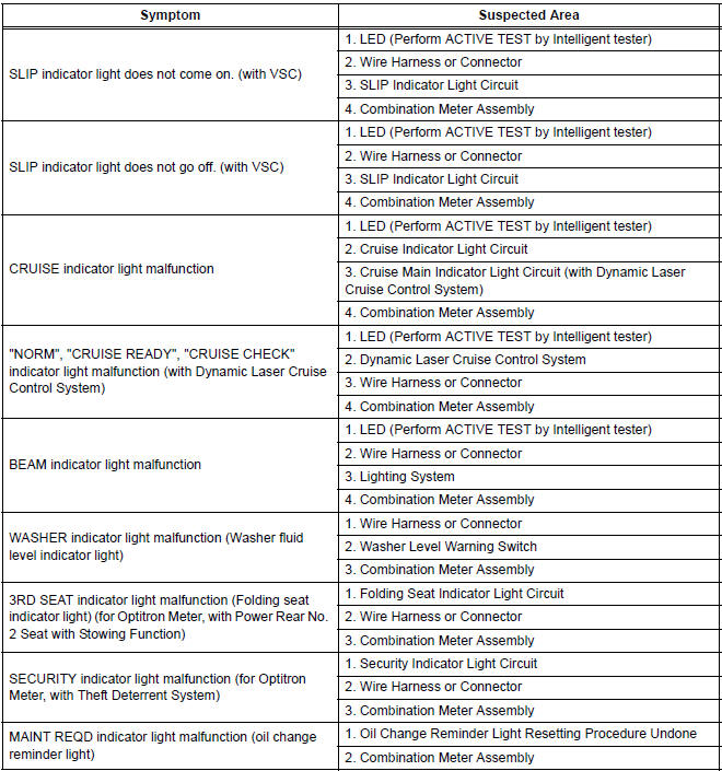
INDICATOR LIGHTS
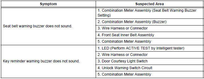
BUZZER
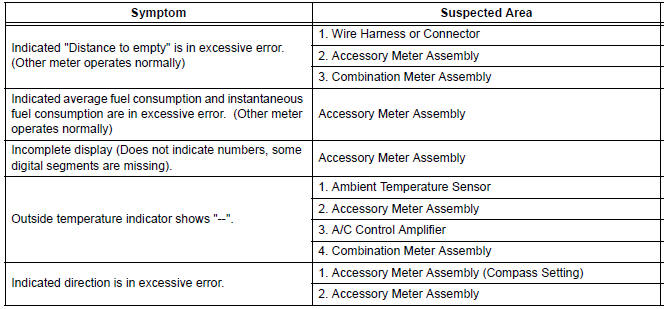
ACCESSORY METER ASSEMBLY
 Customize parameters
1. Seat Belt Buzzer ON/OFF Setting
The seat belt buzzer ON/OFF setting, which is a setting
of the buzzer function of the combination meter, can
disable the driver side seat belt buzzer and front
p ...
 Terminals of ECU
1. COMBINATION METER ASSEMBLY
*1: with Power Rear No. 2 Seat with Stowing Function
*2: with Theft Deterrent System
Waveform 1 (Reference) : Using an oscilloscope:
OK ...
Other materials:
Disassembly
1. REMOVE STEERING INTERMEDIATE SHAFT ASSEMBLY
(a) Align the matchmarks on the steering intermediate
shaft assembly and main shaft.
(b) Remove the bolt and steering intermediate shaft
assembly.
2. REMOVE KEY CYLINDER LIGHT ASSEMBLY (w/o
Engine Immobiliser System)
3. REMOVE TRANSPONDER K ...
Brake Warning Light Remains ON
DESCRIPTION
If the ECU detects a trouble, it turns on the brake warning light at the same
time of prohibiting ABS
control.
At this time, the ECU records a DTC in memory.
Connect terminals TC and CG of the DLC3 to make the brake warning light blink
and output the DTC.
WIRING DIAGRAM
...
On-vehicle inspection
1. INSPECT CURTAIN SHIELD AIRBAG ASSEMBLY
(VEHICLE NOT INVOLVED IN COLLISION)
Perform a diagnostic system check.
With the curtain shield airbag assembly installed on
the vehicle, perform a visual check. If there are any
defects as mentioned below, replace the front pillar
garn ...
