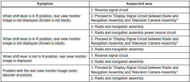
Toyota Sienna Service Manual: Problem symptoms table
- Before inspecting the suspected areas listed in the table below, check the fuse and relay.
- Before inspecting the suspected areas listed in the table below, check the DTCs.
- Methods used to verify the cause of the problem are listed in order of probability in the suspected area column.
REAR VIEW MONITOR SYSTEM
 How to proceed with
troubleshooting
How to proceed with
troubleshooting
1 VEHICLE BROUGHT TO WORKSHOP
2 CUSTOMER PROBLEM ANALYSIS
3 CHECK AND CLEAR DTCs
Refer to the diagnostic check/clear
4 PROBLEM SYMPTOM CONFIRMATION
5 SYMPTOM SIMULATION
6 CHECK DTC
7 CHECK ...
 Terminals of ECU
1. TELEVISION CAMERA ASSEMBLY
Disconnect the T10 camera connector
Measure the voltage and resistance of each
terminal of the wire harness side connector.
If the result is ...
Other materials:
Disassembly
1. REMOVE BACK DOOR GARNISH CENTER
Using a clip remover, disengage the 5 clips and
remove the garnish center.
2. REMOVE BACK DOOR SIDE GARNISH LH
Using a clip remover, disengage the 3 clips and
remove the side garnish.
3. REMOVE BACK DOOR SIDE GARNISH RH
Using a clip remove ...
GCWR, TWR and Unbraked TWR
Confirm that the gross trailer weight, gross combination weight, gross
vehicle weight, gross axle weight and tongue weight are all within the
limits.
GCWR*
2WD models: 8900 lb. (4037 kg)
AWD models: 8990 lb. (4078 kg)
TWR*
3500 lb. (1588 kg)
Unbraked TWR*
1000 lb. (454 kg)
*: These models ...
Evaporative Emission System Switching Valve Control Circuit High
DTC SUMMARY
DESCRIPTION
The circuit description can be found in the EVAP (Evaporative Emission)
System (See page ES-404).
INSPECTION PROCEDURE
Refer to the EVAP System (See page ES-404).
MONITOR DESCRIPTION
5 hours*1 after the ignition switch is turned off, the electric vacuum pump
...
