Toyota Sienna Service Manual: –°amshaft timing oil control valve assembly
COMPONENTS
ON-VEHICLE INSPECTION
1. INSPECT CAMSHAFT TIMING CONTROL VALVE ASSEMBLY
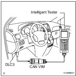
(a) Connect the intelligent tester to the DLC3.
(b) Turn the ignition switch to the ON position.
(c) Start the engine and warm it up.
(d) Select the intelligent tester from the ACTIVE TEST menu.
(e) Check the engine speed when the OCV (camshaft timing oil control valve) is operated by the intelligent tester.
OK 
REMOVAL
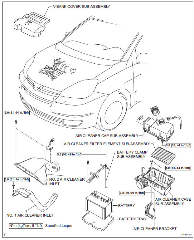
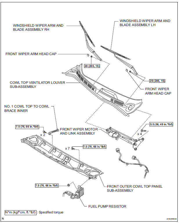
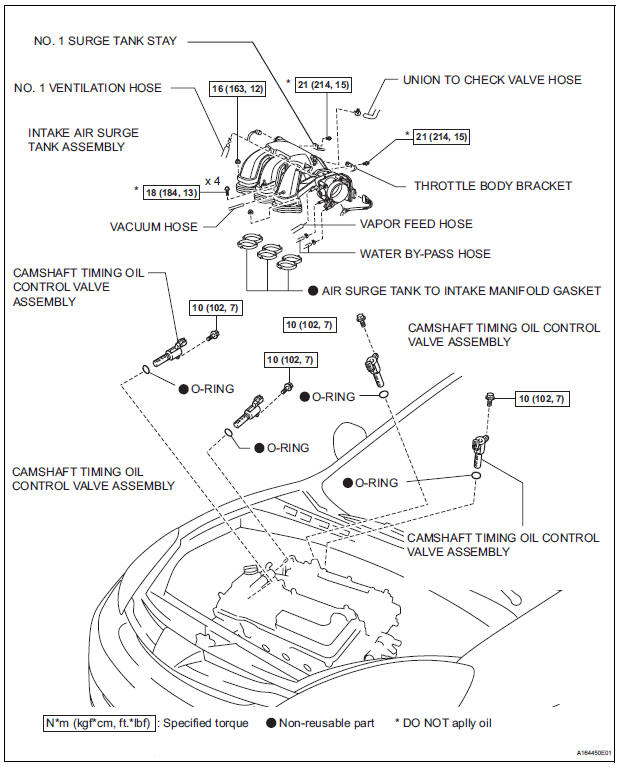
1. REMOVE WINDSHIELD WIPER MOTOR ASSEMBLY HINT: (See page WW-4) 2. REMOVE FRONT OUTER COWL TOP PANEL SUBASSEMBLY (See page EM-27) 3. DRAIN ENGINE COOLANT (See page CO-6) 4. REMOVE V-BANK COVER SUB-ASSEMBLY (See page EM-28) 5. REMOVE NO. 2 AIR CLEANER INLET (See page EM- 28) 6. REMOVE NO. 1 AIR CLEANER INLET (See page EM- 28) 7. REMOVE AIR CLEANER CAP SUB-ASSEMBLY (See page ES-493) 8. REMOVE AIR CLEANER CASE SUB-ASSEMBLY (See page EM-28) 9. REMOVE INTAKE AIR SURGE TANK ASSEMBLY (See page ES-521) 10. REMOVE CAMSHAFT TIMING OIL CONTROL VALVE ASSEMBLY (for Bank 1 Exhaust Side)
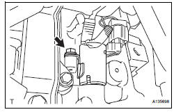
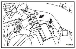
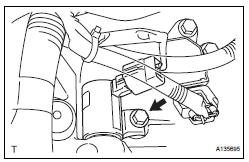
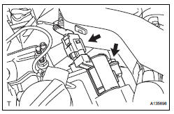
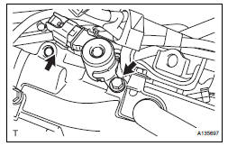
(a) Disconnect the camshaft timing oil control valve assembly connector.
(b) Remove the bolt and camshaft timing oil control valve assembly.
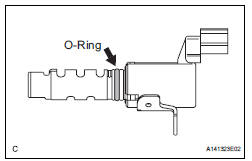
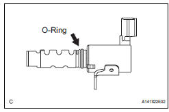
(c) Remove the O-ring from the camshaft timing oil control valve.
11. REMOVE CAMSHAFT TIMING OIL CONTROL VALVE ASSEMBLY (for Bank 1 Intake Side)
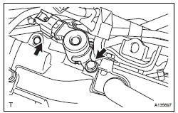
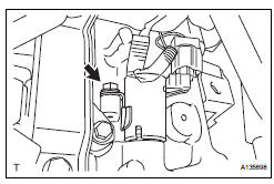
(a) Disconnect the camshaft timing oil control valve assembly connector.
(b) Remove the bolt and camshaft timing oil control valve assembly.
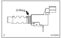
(c) Remove the O-ring from the camshaft timing oil control valve.
12. REMOVE CAMSHAFT TIMING OIL CONTROL VALVE ASSEMBLY (for Bank 2 Exhaust Side)
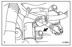
(a) Disconnect the camshaft timing oil control valve assembly connector.
(b) Remove the bolt and camshaft timing oil control valve assembly.
(c) Remove the O-ring from the camshaft timing oil control valve.
13. REMOVE CAMSHAFT TIMING OIL CONTROL VALVE ASSEMBLY (for Bank 2 Intake Side)
(a) Disconnect the camshaft timing oil control valve assembly connector.
(b) Remove the bolt and camshaft timing oil control valve assembly.
(c) Remove the O-ring from the camshaft timing oil control valve.
INSPECTION
1. INSPECT CAMSHAFT TIMING OIL CONTROL VALVE ASSEMBLY
(a) Resistance inspection
(1) Using an ohmmeter, measure the resistance between the terminals.
Resistance: 6.9 to 7.9 Ω at 20¬∞C (68¬∞F)
If necessary, replace the camshaft timing oil control valve assembly.
(b) Movement inspection
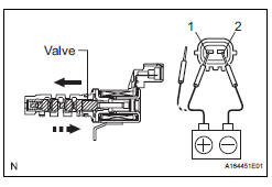
(1) Connect the positive (+) lead from the battery to terminal 1 and connect the negative (-) lead to terminal 2, and check the movement of the valve.
| NOTICE: Confirm that the valve moves freely and does not stick in any position. |
If necessary, replace the camshaft timing oil control valve assembly.
HINT: Accumulation of foreign objects causes subtle pressure leaks. The subtle pressure leaks will cause the cam to advance, and this will cause a DTC to be set.
INSTALLATION
1. INSTALL CAMSHAFT TIMING OIL CONTROL VALVE ASSEMBLY (for Bank 2 Exhaust Side)
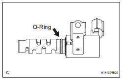
(a) Apply a light coat of engine oil to the new O-ring and install it to the camshaft timing oil control valve.
(b) Install the camshaft timing oil control valve assembly with the bolt.
Torque: 10 N*m (102 kgf*cm, 7 ft.*lbf) (c) Connect the camshaft timing oil control valve assembly connector.
2. INSTALL CAMSHAFT TIMING OIL CONTROL VALVE ASSEMBLY (for Bank 2 Intake Side)
(a) Apply a light coat of engine oil to the new O-ring and install it to the camshaft timing oil control valve.
(b) Install the camshaft timing oil control valve assembly with the bolt.
Torque: 10 N*m (102 kgf*cm, 7 ft.*lbf) Connect the camshaft timing oil control valve assembly connector.
3. INSTALL CAMSHAFT TIMING OIL CONTROL VALVE ASSEMBLY (for Bank 1 Exhaust Side)
(a) Apply a light coat of engine oil to the new O-ring and install it to the camshaft timing oil control valve.
(b) Install the camshaft timing oil control valve assembly with the bolt.
Torque: 10 N*m (102 kgf*cm, 7 ft.*lbf) (c) Connect the camshaft timing oil control valve assembly connector.
4. INSTALL CAMSHAFT TIMING OIL CONTROL VALVE ASSEMBLY (for Bank 1 Intake Side)
(a) Apply a light coat of engine oil to the new O-ring and install it to the camshaft timing oil control valve.
(b) Install the camshaft timing oil control valve assembly with the bolt.
Torque: 10 N*m (102 kgf*cm, 7 ft.*lbf) (c) Connect the camshaft timing oil control valve assembly connector.
5. INSTALL INTAKE AIR SURGE TANK ASSEMBLY (See page ES-522) 6. INSTALL AIR CLEANER CASE SUB-ASSEMBLY (See page EM-59) 7. INSTALL AIR CLEANER CAP SUB-ASSEMBLY (See page ES-496) 8. INSTALL NO. 1 AIR CLEANER INLET (See page EM- 59) 9. INSTALL NO. 2 AIR CLEANER INLET (See page EM- 60) 10. ADD ENGINE COOLANT (See page CO-7) 11. INSPECT FOR ENGINE COOLANT LEAK (See page CO-1) 12. INSPECT FOR ENGINE OIL LEAK (See page LU-6) 13. INSTALL V-BANK COVER SUB-ASSEMBLY (See page EM-63) 14. INSTALL FRONT OUTER COWL TOP PANEL SUBASSEMBLY (See page EM-61) 15. INSTALL WINDSHIELD WIPER MOTOR ASSEMBLY HINT: (See page WW-5)
 MIL Circuit
DESCRIPTION
The MIL (Malfunction Indicator Lamp) is used to indicate vehicle malfunctions
detected by the ECM.
When the ignition switch is turned to the ON position, power is supplied to the
M ...
 Throttle body
COMPONENTS
...
Other materials:
Drive belt
COMPONENTS
REMOVAL
1. REMOVE FRONT WHEEL RH
2. REMOVE FRONT FENDER APRON SEAL RH (See
page EM-26)
3. REMOVE V-RIBBED BELT
(a) Using SST, release the belt tension by turning the
belt tensioner counterclockwise, and remove the Vribbed
belt from the belt tensioner.
SST 09249-63010
(b) ...
Front Fog Light Circuit
DESCRIPTION
The Multiplex network body ECU controls FOG relay when signal is received
from headlight dimmer
switch assembly.
WIRING DIAGRAM
INSPECTION PROCEDURE
1 PERFORM ACTIVE TEST BY INTELLIGENT TESTER
Connect the intelligent tester to DLC3.
Turn the ignition switch ON and push t ...
Engine Coolant Temperature Circuit Range /
Performance Problem
DTC P0116 Engine Coolant Temperature Circuit Range /
Performance Problem
DESCRIPTION
Refer to DTC P0115
DTC No.
DTC Detection Condition
Trouble Area
P0116
ECTs as listed below are nearly same (2 trip detection
logic):
ECT when engine is start ...
