Toyota Sienna Service Manual: Radio and Navigation Assembly Communication Error
INSPECTION PROCEDURE
1 IDENTIFY THE COMPONENT SHOWN BY THE SUB-CODE
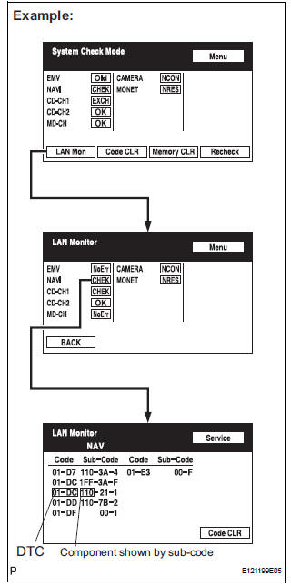
- Enter the diagnostic mode.
- Press the "LAN Mon" switch to change to "LAN Monitor" mode.
- Identify the component shown by the sub-code.
HINT:
- "110 (multi-display)" is the component shown by the sub-code in the example shown in the illustration.
- The sub-code will be indicated by its physical address.
- For the component list, refer to "DIAGNOSIS DISPLAY DETAILED DESCRIPTION"
2 CHECK POWER SOURCE CIRCUIT OF COMPONENT SHOWN BY SUB-CODE
- Inspect the power source circuit of the component shown
by the sub-code.
If the power source circuit is operating normally, proceed to the next step
Component Table:

3 CHECK RADIO AND NAVIGATION ASSEMBLY
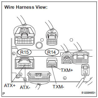
- Disconnect the radio and navigation assembly.
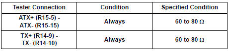
- Measure the resistance according to the value(s) in the table below.
Standard resistance
4 CHECK HARNESS AND CONNECTOR
HINT:
- Start the check from the circuit that is near the component shown by the sub-code first.
- For details of the connectors, refer to "TERMINALS OF ECU".
- Referring to the AVC-LAN wiring diagram below, check the AVC-LAN circuit between the radio and navigation assembly and the component shown by the sub-code.
- Disconnect all connectors between the radio and navigation assembly and the component shown by sub-code.
- Check for an open or short in the AVC-LAN circuit between the radio and navigation assembly and the component shown by the sub-code
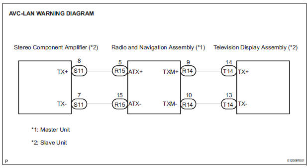
OK: There is no open or short circuit.
5 REPLACE COMPONENT SHOWN BY SUB-CODE
- Replace the component shown by the sub-code with a normal one and check if the same problem occurs again.
OK: Same problem does not occur.
END
 Stereo Component Amplifier Communication Error
INSPECTION PROCEDURE
1 IDENTIFY THE COMPONENT SHOWN BY THE SUB-CODE
Enter the diagnostic mode.
Press the "LAN Mon" switch to change to "LAN Monitor"
mode.
&nbs ...
 Television Display Assembly Communication Error
INSPECTION PROCEDURE
1 IDENTIFY THE COMPONENT SHOWN BY THE SUB-CODE
Enter the diagnostic mode.
Press the "LAN Mon" switch to change to "LAN Monitor"
mode.
&nbs ...
Other materials:
Passenger Side Buckle Switch Circuit Malfunction
DTC B1771 Passenger Side Buckle Switch Circuit Malfunction
DESCRIPTION
The passenger side buckle switch circuit consists of the occupant
classification ECU and the front seat
inner belt assembly RH.
DTC B1771 is recorded when a malfunction is detected in the passenger side
buckle switch ci ...
Initialization procedure
(a) Make sure that the ignition switch is off.
(b) Connect the intelligent tester to the DLC3.
(c) Turn the ignition switch to the ON position.
(d) Select "TIREPRESS" by following the prompts
displayed on the intelligent tester.
(e) Press the tire pressure warning reset sw ...
Reassembly
1. INSTALL IGNITION OR STARTER SWITCH
ASSEMBLY
(a) Install the ignition or starter switch assembly to the
steering column bracket assembly UPR with the 2
screws.
2. INSTALL KEY INTER LOCK SOLENOID
(a) Install the solenoid to the steering column bracket
assembly with the 2 screws.
3. INSTALL ...
