Toyota Sienna Service Manual: Radio Broadcast cannot be Received or Poor Reception
INSPECTION PROCEDURE
1 CHECK RADIO RECEIVER
- Check the radio's automatic station search function.
- Check the radio's automatic station search function by activating it.
OK: The radio's automatic station search function works properly.
2 CONFIRM MODEL
Result

3 INSPECT RADIO RECEIVER ASSEMBLY
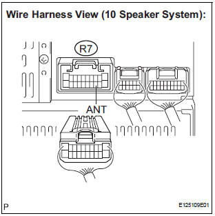
- Disconnect the radio receiver connector R7.
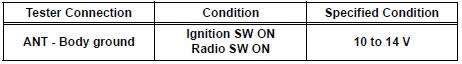
- Measure the voltage according to the value(s) in the table below.
Standard voltage
4 CHECK OPTIONAL COMPONENTS
- Check optional components (sun-shade film, telephone antenna, etc.).
- Check if any optional components, such as sunshade film or telephone antenna that may decrease reception capacity, are installed.
OK: Optional components are installed.
NOTICE: Do not remove any optional components installed by the customer without his or her consent.
5 CHECK RADIO RECEIVER
- Preparation for check
- Remove the antenna plug from the radio receiver.
- Check for noise
- Turn the ignition switch to the ACC position with the radio receiver connector connected.
- Turn the radio on and put into AM mode.
- Place a screwdriver, thin wire, or other metal object on the radio receiver's antenna jack and check that noise can be heard from the speaker.
OK: Noise occurs
6 CHECK GLASS ANTENNA
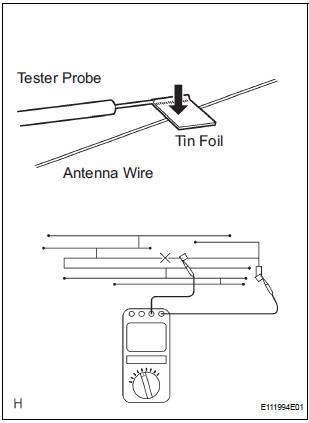
- Check for continuity of the antenna.
HINT: Check for continuity at the center of each antenna wire as shown in the illustration.
NOTICE: When cleaning the glass, wipe it in the direction of the wire with a soft dry cloth. Take care not to damage the wire. Do not use detergents or glass cleaners with abrasive ingredients. When measuring voltage, wrap a piece of tin foil around the tip of the negative probe and press the foil against the wire with your finger, as shown in the illustration.
OK: There is continuity in the antenna.
7 CHECK ANTENNA CORD
- Remove the antenna plug of the radio receiver and antenna.
- Measure the resistance between the antenna and radio
receiver to check for an open circuit in the antenna cord.
Standard resistance: Below 1 Ω
- Measure the resistance between the antenna cord and
body ground to check for a short circuit in the antenna
cord.
Standard resistance: 10 kΩ or higher
8 REPLACE AMPLIFIER ANTENNA ASSEMBLY
- Replace the amplifier antenna and check if radio broadcasts can be received normally.
OK: Radio broadcasts can be received.
REPLACE RADIO RECEIVER
9 CHECK OPTIONAL COMPONENTS
- Check optional components (sun-shade film, telephone antenna, etc.).
- Check if any optional components, such as sunshade film or telephone antenna that may decrease reception capacity, are installed.
OK: Optional components are installed.
NOTICE: Do not remove any optional components installed by the customer without his or her consent.
10 CHECK RADIO RECEIVER
- Preparation for check
- Remove the antenna plug from the radio receiver.
- Check for noise
- Turn the ignition switch on (ACC) with the radio receiver connector connected.
- Turn the radio on and put into AM mode.
- Place a screwdriver, thin wire, or other metal object on the radio receiver's antenna jack and check that noise can be heard from the speaker.
OK: Noise occurs.
11 CHECK RADIO ANTENNA CO
- Remove the antenna plug of the radio receiver and antenna.
- Measure the resistance between the antenna and radio receiver to check for an open circuit in the radio antenna cord.
Standard resistance: Below 1 Ω
- Measure the resistance between the radio antenna cord and body ground to check for a short circuit in the antenna cord.
Standard resistance: 10 kΩ or higher
12 REPLACE ANTENNA POLE
- Replace antenna pole and check that it operated normally.
OK: The antenna pole operates normally.
REPLACE RADIO RECEIVER
 CD Sound Skips
INSPECTION PROCEDURE
1 CHECK CD
Check the CD.
OK:
The CD is clean.
HINT:
If dirt is on the CD surface, wipe it clean with a soft cloth
from the inside to the outside in a radial direct ...
 Poor Sound Quality in All Modes (Low Volume)
INSPECTION PROCEDURE
1 CHECK AUDIO SETTINGS
Set "BASS", "MID", and "TREB" to the initial values and
check that sound is normal.
OK:
Malfunction disappears.
2 ...
Other materials:
Perform signal check
HINT:
When entering signal check mode, the tire pressure
warning ECU sets all the signal check DTCs first.
After completing signal check for each inspection
item, the DTCs for systems that are determined to be
normal by the tire pressure warning ECU will be
erased.
The DTCs f ...
Slide Door Closer RH does not Operate
DESCRIPTION
The slide door ECU RH controls the slide door closer. In response to the
signals output from the switches
in the slide door lock, the slide door closer drives the closer motor.
HINT:
The slide door closer system operates regardless of the power slide door main
switch ON / OFF.
W ...
CD Player Mechanical Error/ CD Insertion and Ejection Error/ CD Reading
Abnormal/ CD Changer Mechanical Error/ CD Insertion and Ejection Error/ CD
Reading Abnormal
DTC 62-10 CD Player Mechanical Error
DTC 62-11 CD Insertion and Ejection Error
DTC 62-12 CD Reading Abnormal
DTC 63-10 CD Changer Mechanical Error
DTC 63-11 CD Insertion and Ejection Error
DTC 63-12 CD Reading Abnormal
DESCRIPTION
DTC No.
DTC Detecting Condition
Troub ...
