Toyota Sienna Service Manual: Radio Receiver Communication Error
INSPECTION PROCEDURE
1 IDENTIFY THE COMPONENT SHOWN BY THE SUB-CODE
- Enter the diagnostic mode
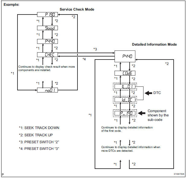
- Press the preset switch "3" to change to "Detailed Information Mode".
- Identify the component shown by the sub-code.
HINT:
- "190 (radio receiver)" is the component shown by the subcode in the example shown in the illustration.
- For details of the DTC display, refer to "DTC CHECK/ CLEAR"
2 CHECK POWER SOURCE CIRCUIT OF COMPONENT SHOWN BY SUB-CODE
- Inspect the power source circuit of the component shown
by the sub-code.
If the power source circuit is operating normally, proceed to the next step.
Component Table:
|
Component |
Proceed to |
| Stereo component amplifier (440) | Stereo component amplifier power source circuit |
| Television display assembly (1B0) | Television display assembly power source circuit |
3 INSPECT RADIO RECEIVER
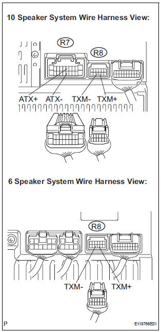
- Disconnect the radio receiver connectors.
- Measure the resistance according to the value(s) in the table below.
Standard resistance
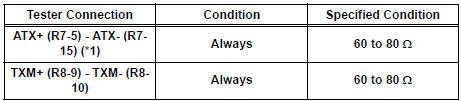
*1: 10 Speaker System
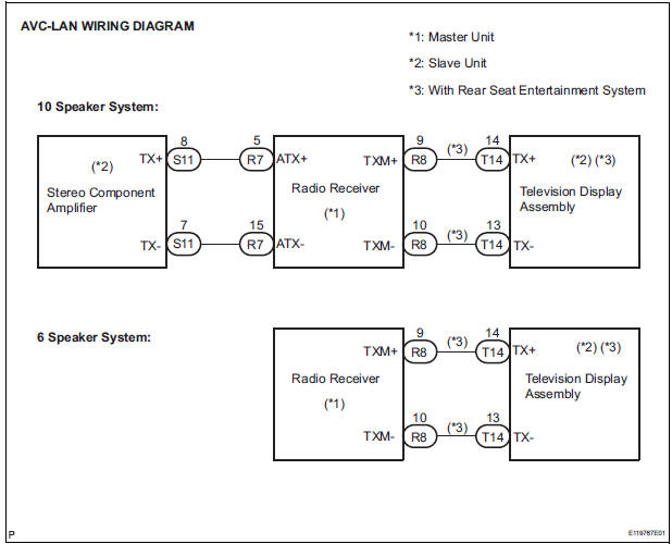
4 CHECK HARNESS AND CONNECTOR (RADIO RECEIVER - COMPONENT SHOWN BY SUB-CODE)
HINT:
- Start the check from the circuit that is near the component shown by the sub-code first.
- For details of the connectors, refer to the "TERMINALS OF ECU".
- Referring to the AVC-LAN wiring diagram below, check the AVC-LAN circuit between the radio receiver and the component shown by the sub-code.
- Disconnect all connectors between the radio receiver and the component shown by sub-code.
- Check for an open or short in the AVC-LAN circuit between the radio receiver and the component shown by the sub-code.
OK: There is no open or short circuit.
5 REPLACE COMPONENT SHOWN BY SUB-CODE
- Replace the component shown by the sub-code with a normal one and check if the same problem occurs again.
OK: Same problem does not occur.
END
 Vehicle Speed Signal Circuit between Stereo Component Amplifier and
Combination Meter
Vehicle Speed Signal Circuit between Stereo Component Amplifier and
Combination Meter
DESCRIPTION
This circuit is necessary for the ASL (Auto Sound Leveliser) built into the
stereo component amplifier.
Speed signals are received from the combination meter and used for the ASL.
...
 Stereo Component Amplifier Communication Error
INSPECTION PROCEDURE
1 IDENTIFY THE COMPONENT SHOWN BY THE SUB-CODE
Enter the diagnostic mode.
Press the preset switch "3" to change to "Detailed
Information Mode" ...
Other materials:
High Temperature
DTC 44-47 High Temperature
DESCRIPTION
DTC No.
DTC Detecting Condition
Trouble Area
44-47
Sensor detects that DVD unit temperature is high.
(Over 80C)
Television display assembly
INSPECTION PROCEDURE
HINT:
After the inspection is completed, ...
Seat Belt Buckle Switch LH Circuit Malfunction
DTC B0126/27 Seat Belt Buckle Switch LH Circuit Malfunction
DESCRIPTION
The seat belt buckle switch LH circuit consists of the center airbag sensor
assembly and the front seat
inner belt assembly LH.
DTC B0126/27 is recorded when a malfunction is detected in the seat belt buckle
switch LH ...
Disc cannot be Played/ No Playable Files/ Copyright Protection Error/ Disc
cannot be Played/ No Playable Files/ Copyright Protection Error
DTC 62-7D Disc cannot be Played
DTC 62-7E No Playable Files
DTC 62-7F Copyright Protection Error
DTC 63-7D Disc cannot be Played
DTC 63-7E No Playable Files
DTC 63-7F Copyright Protection Error
DESCRIPTION
INSPECTION PROCEDURE
HINT:
After the inspection is completed, clear the DTCs.
1 ...
