Toyota Sienna Service Manual: Rear Blower Motor Circuit
DESCRIPTION
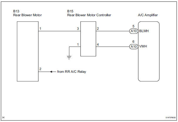
Power to the rear blower motor is supplied from the battery via the RR A/C relay.
The rear blower motor speed level varies between 0 and 31 based on the voltage difference measured between the terminals of the motor.
The voltage difference measured between the terminals of the rear blower motor changes in proportion to the control at the rear blower motor controller on the ground side.
WIRING DIAGRAM
INSPECTION PROCEDURE
1 READ VALUE OF INTELLIGENT TESTER
(a) Connect the intelligent tester to the DLC3.
(b) Turn the ignition switch to the ON position and turn the intelligent tester main switch on.
(c) Select the item below in the DATA LIST, and read the display on the intelligent tester.
DATA LIST / AIR CONDITIONER 
OK: The display is as specified in the normal condition.

PROCEED TO NEXT CIRCUIT INSPECTION SHOWN IN PROBLEM SYMPTOMS TABLE
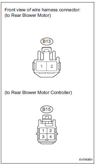
2 INSPECT REAR BLOWER MOTOR
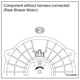
(a) Remove the rear blower motor with the connector still connected.
(b) Disconnect the connector from the rear blower motor.
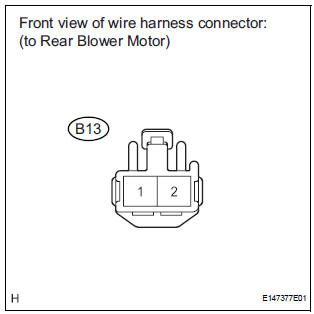
(c) Connect the positive (+) lead to terminal 1 of the rear blower motor connector, and the negative (-) lead to terminal 2.
OK: The rear blower motor operates smoothly.


3 CHECK HARNESS AND CONNECTOR (REAR BLOWER MOTOR - BATTERY)
(a) Measure the voltage according to the value(s) in the table below.
Standard voltage 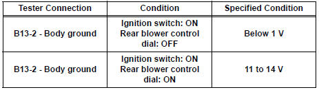
4 CHECK HARNESS AND CONNECTOR (REAR BLOWER MOTOR CONTROLLER - BODY GROUND)
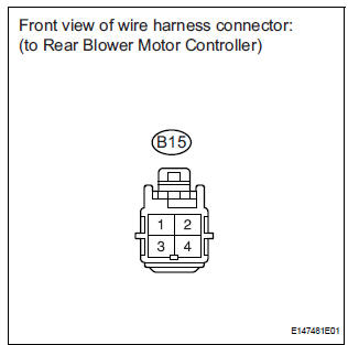
(a) Disconnect the connector from the rear blower motor controller.
(b) Measure the resistance according to the value(s) in the table below.
Standard resistance 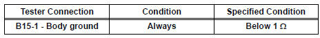


5 CHECK HARNESS AND CONNECTOR (REAR BLOWER MOTOR - REAR BLOWER MOTOR CONTROLLER)
(a) Measure the resistance according to the value(s) in the table below.
Standard resistance 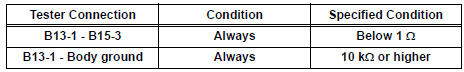


6 CHECK HARNESS AND CONNECTOR (REAR BLOWER MOTOR CONTROLLER - A/C AMPLIFIER)
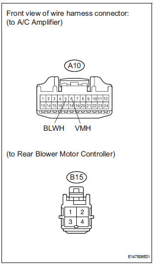
(a) Disconnect the connector from the A/C amplifier.
(b) Measure the resistance according to the value(s) in the table below.
7 INSPECT REAR BLOWER MOTOR CONTROLLER
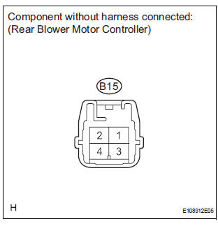
(a) Disconnect the connector from the rear blower motor controller.
(b) Measure the resistance according to the value(s) in the table below.
Standard resistance 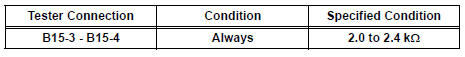
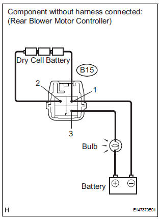
(c) Connect the positive (+) lead to terminal 3 through a 12 V 3.4 W test bulb, and the negative (-) lead to terminal 1.
(d) Connect the three 1.5 V dry cell batteries' positive (+) lead to terminal 2, and the negative (-) lead to terminal 1.
Then check that the test bulb comes on.
OK: The test bulb comes on.

PROCEED TO NEXT CIRCUIT INSPECTION SHOWN IN PROBLEM SYMPTOMS TABLE
 Rear Air Conditioning Relay Circuit
DESCRIPTION
The RR A/C relay is switched on by signals from the A/C amplifier. It
supplies power to the rear blower
motor.
WIRING DIAGRAM
INSPECTION PROCEDURE
1 INSPECT RELAY (RR A/C)
...
 IG Power Source Circuit
DESCRIPTION
The main power source is supplied to the A/C amplifier when the ignition
switch is turned to the ON
position.
The power source is used for operating the A/C amplifier and servo moto ...
Other materials:
Air conditioning controls
Adjusting the temperature setting
Press “” on the “TEMP” button to
increase the temperature and “”
to decrease the temperature.
Adjusting the fan speed
Press “” on
to increase the fan speed and “”
to decrease
the fan speed.
Press the “OFF” button to turn the ...
System normal condition check
1. CHECK NORMAL CONDITION
If the symptom is applicable to any of the following,
it is intended behavior, and not a malfunction.
Symptom
Answer
A longer route than expected is chosen.
Depending on the road conditions, the radio and navigation assembly
m ...
TS and CG Terminal Circuit
DESCRIPTION
The Test Mode (signal check) circuit detects trouble in the sensor or switch
signal, which cannot be
detected by the DTC check.
Connecting terminals TS and CG of the DLC3 starts the check.
WIRING DIAGRAM
INSPECTION PROCEDURE
1 CHECK HARNESS AND CONNECTOR (BETWEEN SKID CONTR ...
