Toyota Sienna Service Manual: Rear differential carrier
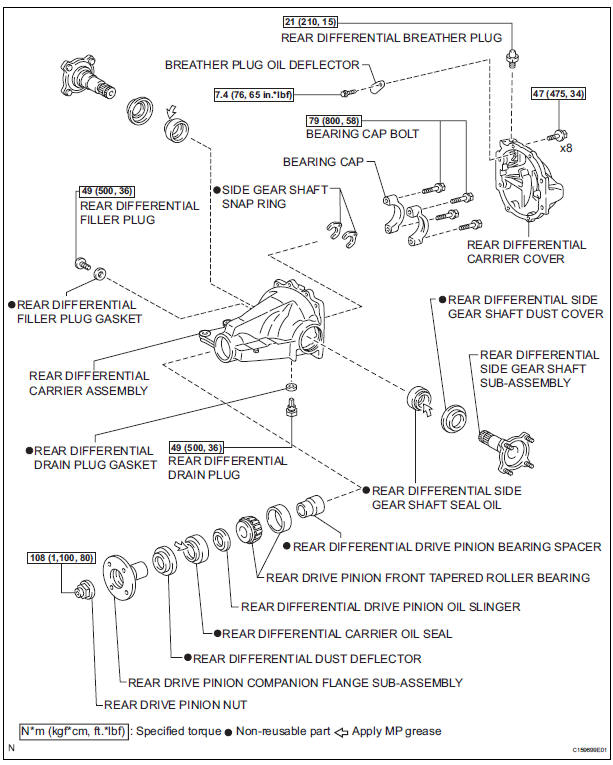
COMPONENTS
 Installation
1. INSTALL NO. 1 REAR DIFFERENTIAL SUPPORT
(a) Install the No. 1 rear differential support to the rear
differential carrier assembly with the 2 bolts and 2
nuts.
Torque: 85 N*m (867 kgf*cm, 63 ...
 Disassembly
1. REMOVE REAR DIFFERENTIAL CARRIER COVER
(a) Remove the 8 bolts from the carrier cover.
(b) Using a brass bar and a hammer, separate the
carrier cover from rear differential carrier assembly ...
Other materials:
Data list / active test
HINT:
By accessing the DATA LIST displayed on the intelligent
tester, you can perform such functions as reading the values
of switches and sensors without removing any parts. Reading
the DATA LIST as the first step in troubleshooting is one
method to shorten labor time.
1. DATA LIST FOR CENTER ...
Towing related terms
GCWR (Gross Combination Weight Rating)
The maximum allowable gross
combination weight. The gross
combination weight is the sum
of the total vehicle weight
(including the occupants, cargo
and any optional equipment
installed on the vehicle) and the
weight of the trailer being towed
(incl ...
If you think something is
wrong
If you notice any of the following symptoms, your vehicle probably
needs adjustment or repair. Contact your Toyota dealer as
soon as possible.
Visible symptoms
Fluid leaks under the vehicle
(Water dripping from the air conditioning after use is normal.)
Flat-looking tires or uneven tire w ...
