Toyota Sienna Service Manual: Rear differential carrier assembly
Components
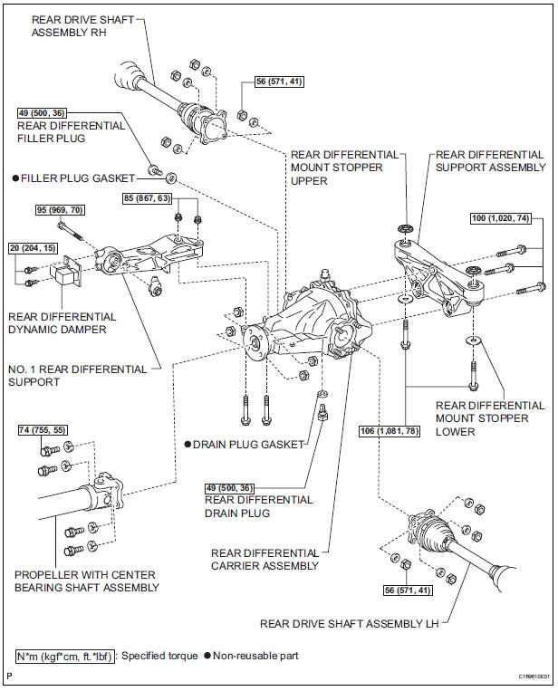
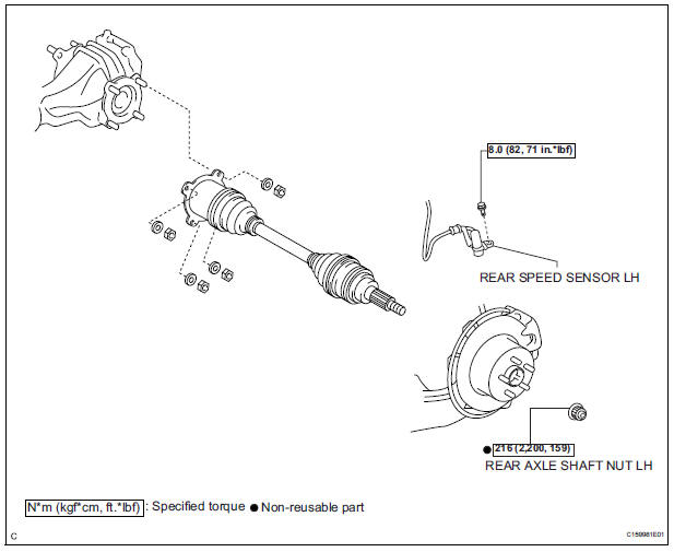
 Installation
1. INSTALL REAR DIFFERENTIAL DRIVE PINION
BEARING SPACER
(a) Install a new bearing spacer.
2. INSTALL REAR DRIVE PINION FRONT TAPERED
ROLLER BEARING
(a) Install the tapered roller bearing.
3. IN ...
 Removal
1. Remove rear wheel
2. Remove exhaust pipe assembly
Hint:
(see page ex-8)
3. Remove propeller with center bearing
shaft assembly
Hint:
(see page pr-3)
4. REMOVE REAR DIFFERENTIAL FILLER PLUG
...
Other materials:
Disassembly
1. REMOVE PARKING BRAKE PEDAL BRACKET PROTECTOR
(a) Using a flat-head screwdriver, disengage the 2
claws on the parking brake pedal bracket protector.
(b) Turning the parking brake pedal bracket protector
clockwise, remove the parking brake pedal bracket
protector from the parking brake ...
Wiper switch
COMPONENTS
REMOVAL
1. REMOVE STEERING COLUMN COVER
2. REMOVE WINDSHIELD WIPER SWITCH ASSEMBLY
Disconnect the connector.
Using a screwdriver, disengage the claw and pull
out the windshield wiper switch assembly.
NOTICE:
The claw will be broken if pressed hard.
HINT ...
Description of initialization
(a) Perform initialization in the following cases:
Before delivery of a new vehicle.
After replacement of the tire pressure warning
ECU*.
After replacement of the tire pressure warning
valve and transmitter.
Specified tire pressure changes depending on
the size or type of the tire.
...
