
Toyota Sienna Service Manual: Rear differential carrier oil seal
COMPONENTS
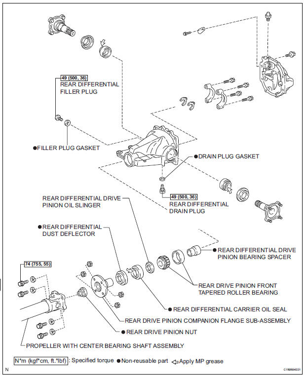
 Differential oil
Adjustment
1. INSPECT DIFFERENTIAL OIL
(a) Stop the vehicle on the level place.
(b) Remove the differential filler plug and gasket.
(c) Check that the oil surface is within 5 mm (0.20 in.) ...
 Removal
1. REMOVE FRONT EXHAUST PIPE ASSEMBLY
HINT:
(See page EX-8)
2. REMOVE PROPELLER WITH CENTER BEARING
SHAFT ASSEMBLY
HINT:
(See page PR-3)
3. REMOVE REAR DIFFERENTIAL FILLER PLUG
(a) Using a hex ...
Other materials:
On-vehicle inspection
1. INSPECT COOLER CONDENSER CORE
(a) If the fin of the cooler condenser core is dirty, clean
it with water and dry it with compressed air.
NOTICE:
Do not damage the fin of the cooler condenser
core.
(b) If the fin of the cooler condenser core is bent, make
it straight using a screwdriver or p ...
Fuel Pump Control Circuit
DESCRIPTION
The FUEL PUMP relay switches the fuel pump speed according to the engine
conditions. The fuel pump
operates when the ECM receives the starter-operating signal (STA) and
crankshaft-rotating signal (NE).
The FUEL PUMP relay is turned ON while the engine is idling or operating at l ...
Video terminal
COMPONENTS
REMOVAL
1. REMOVE REAR DOOR SCUFF PLATE LH
2. REMOVE REAR DOOR WEATHERSTRIP LH
3. REMOVE BACK DOOR WEATHERSTRIP
4. REMOVE BACK DOOR SCUFF PLATE
5. REMOVE QUARTER TRIM FRONT PANEL ASSEMBLY LH
6. REMOVE VIDEO(VIDEO ADAPTER) TERMINAL
Release the 4 claw fittings and ...
