Toyota Sienna Service Manual: Rear evaporator temperature sensor circuit
DESCRIPTION
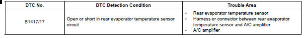
The rear evaporator temperature sensor is installed on the rear evaporator. It detects the rear evaporator temperature. The sensor sends a signal to the A/C amplifier. The resistance of the rear evaporator temperature sensor changes in accordance with the rear evaporator temperature. As the temperature decreases, the resistance increases. As the temperature increases, the resistance decreases.
The A/C amplifier applies voltage (5 V) to the rear evaporator temperature
sensor and reads voltage
changes as the resistance of the rear evaporator temperature sensor changes.
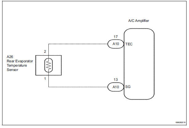
WIRING DIAGRAM
INSPECTION PROCEDURE
1 READ VALUE OF INTELLIGENT TESTER
(a) Connect the intelligent tester to the DLC3.
(b) Turn the ignition switch to the ON position and turn the intelligent tester main switch on.
(c) Select the item below in the DATA LIST, and read the display on the intelligent tester.
DATA LIST / AIR CONDITIONER: 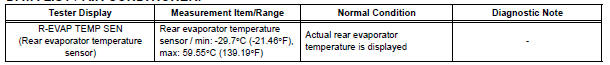
OK: The display is as specified in the normal condition column.
Result 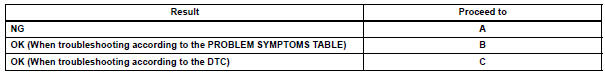

2 INSPECT REAR EVAPORATOR TEMPERATURE SENSOR
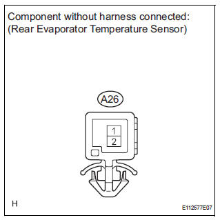
(a) Remove the rear evaporator temperature sensor.
(b) Measure the resistance according to the value(s) in the table below.
Standard resistance 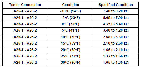
NOTICE:
- Even slightly touching the sensor may change the resistance value. Be sure to hold the connector of the sensor.
- When measuring, the sensor temperature must be the same as the rear evaporator temperature.
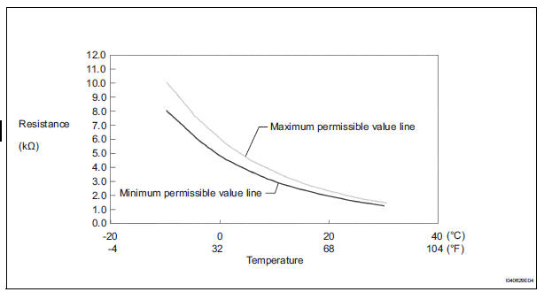
HINT: As the temperature increases, the resistance decreases (see the graph).

3 CHECK HARNESS AND CONNECTOR (REAR EVAPORATOR TEMPERATURE SENSOR - A/C AMPLIFIER)
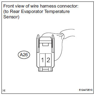
(a) Disconnect the rear evaporator temperature sensor connector.
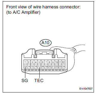
(b) Disconnect the A/C amplifier connector.
(c) Measure the resistance according to the value(s) in the table below.
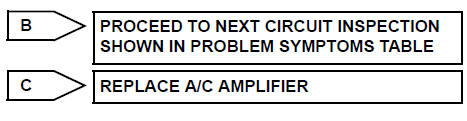
Standard resistance 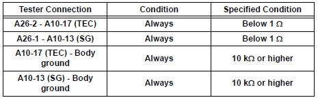

REPLACE A/C AMPLIFIER
 Evaporator temperature sensor circuit
DESCRIPTION
The evaporator temperature sensor (A/C thermistor) is installed on the
evaporator in the air conditioning
unit. It detects the temperature of the cooled air that has passed through the ...
 Rear Room Temperature Sensor Circuit
DESCRIPTION
This sensor detects the rear cabin temperature that is used as the basis for
temperature control and
sends a signal to the A/C amplifier.
WIRING DIAGRAM
INSPECTION PROCEDURE
1 R ...
Other materials:
Problem symptoms table
HINT:
Before inspecting the suspected areas listed in the table
below, check the fuse and relay.
Before inspecting the suspected areas listed in the table
below, check the DTCs.
Methods used to verify the cause of the problem are listed
in order of probability in the ...
Camshaft Position "A" Actuator Circuit
DTC P0010 Camshaft Position "A" Actuator Circuit (Bank
1)
DTC P0020 Camshaft Position "A" Actuator Circuit (Bank
2)
DESCRIPTION
The Variable Valve Timing (VVT) system includes the ECM, Oil Control Valve (OCV)
and VVT controller.
The ECM sends a target duty-cycle control ...
Communication Error from ECM to VSC
DTC P1631 Communication Error from ECM to VSC
DTC U0100 Lost Communication with ECM/PCM "A"
DESCRIPTION
The ECM sends signals such as A/T information signals, dynamic laser cruise
control operation signals,
brake operation demand signals, and buzzer operation demand signals to the sk ...
