Toyota Sienna Service Manual: Rear Occupant Classification Sensor LH Circuit Malfunction
DTC B1782 Rear Occupant Classification Sensor LH Circuit Malfunction
DESCRIPTION
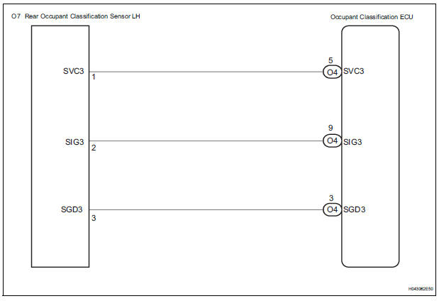
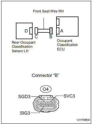
The rear occupant classification sensor LH circuit consists of the occupant classification ECU and the rear occupant classification sensor LH.
DTC B1782 is recorded when a malfunction is detected in the rear occupant classification sensor LH circuit.
|
DTC No. |
DTC Detecting Condition |
Trouble Area |
|
B1782 |
|
|
WIRING DIAGRAM
INSPECTION PROCEDURE
HINT:
- If troubleshooting (wire harness inspection) is difficult to perform, remove the front passenger seat installation bolts to see the under surface of the seat cushion.
- In the above case, hold the seat so that it does not fall down. Holding the seat for a long period of time may cause a problem, such as seat rail deformation. Hold the seat only as necessary.
1 CHECK DTC
- Turn the ignition switch to the ON position.
- Clear the DTCs stored in the memory.
HINT: First clear DTCs stored in the occupant classification ECU and then in the center airbag sensor assembly.
- Turn the ignition switch to the LOCK position.
- Turn the ignition switch to the ON position.
- Check the DTCs (35).
OK: DTC B1782 is not output. HINT: Codes other than DTC B1782 may be output at this time, but they are not related to this check
 USE SIMULATION METHOD TO CHECK

2 CHECK CONNECTION OF CONNECTORS
- Turn the ignition switch to the LOCK position.
- Disconnect the negative (-) terminal cable from the battery, and wait for at least 90 seconds.
- Check that the connectors are properly connected to the occupant classification ECU and the rear occupant classification sensor LH.
OK: The connectors are connected.
 CONNECT CONNECTORS, THEN GO
TO
STEP 1
CONNECT CONNECTORS, THEN GO
TO
STEP 1

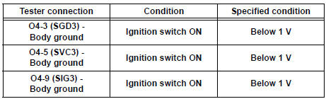
3 CHECK FRONT SEAT WIRE RH (SHORT TO B+)

- Disconnect the connectors from the occupant classification ECU and the rear occupant classification sensor LH.
- Connect the negative (-) terminal cable to the battery.
- Turn the ignition switch to the ON position.
- Measure the voltage according to the value(s) in the table below.
Standard voltage
 REPAIR OR REPLACE FRONT SEAT
WIRE
RH
REPAIR OR REPLACE FRONT SEAT
WIRE
RH

4 CHECK FRONT SEAT WIRE RH (OPEN)
- Turn the ignition switch to the LOCK position.
- Disconnect the negative (-) terminal cable from the battery, and wait for at least 90 seconds.
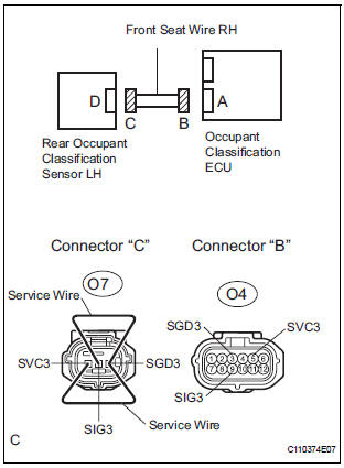
- Using a service wire, connect O7-1 (SVC3) and O7-3
(SGD3), and connect O7-2 (SIG3) and O7-3 (SGD3) of
connector "C".
NOTICE: Do not forcibly insert a service wire into the terminals of the connector when connecting.
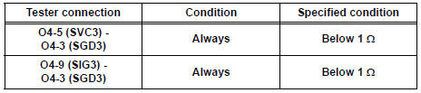
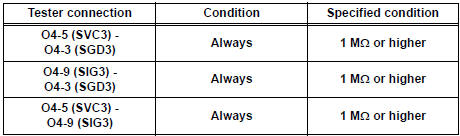
- Measure the resistance according to the value(s) in the table below.
Standard resistance
 REPAIR OR REPLACE FRONT SEAT
WIRE
RH
REPAIR OR REPLACE FRONT SEAT
WIRE
RH

5 CHECK FRONT SEAT WIRE RH (SHORT)
- Disconnect the service wire from connector "C".
- Measure the resistance according to the value(s) in the table below.
Standard resistance
 REPAIR OR REPLACE FRONT SEAT
WIRE
RH
REPAIR OR REPLACE FRONT SEAT
WIRE
RH

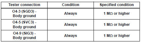
6 CHECK FRONT SEAT WIRE RH (SHORT TO GROUND)
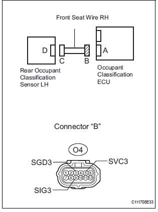
- Measure the resistance according to value(s) in the table below.
Standard resistance
 REPAIR OR REPLACE FRONT SEAT
WIRE
RH
REPAIR OR REPLACE FRONT SEAT
WIRE
RH

7 CHECK DTC
- Connect the connectors to the occupant classification ECU and the rear occupant classification sensor LH.
- Connect the negative (-) terminal cable to the battery
- Turn the ignition switch to the ON position.
- Clear the DTCs stored in the memory.
HINT: First clear DTCs stored in the occupant classification ECU and then in the center airbag sensor assembly.
- Turn the ignition switch to the LOCK position.
- Turn the ignition switch to the ON position.
- Check the DTCs (35).
OK: DTC B1782 is not output. HINT: Codes other than DTC B1782 may be output at this time, but they are not related to this check.
 USE SIMULATION METHOD TO CHECK

8 REPLACE OCCUPANT CLASSIFICATION ECU
- Turn the ignition switch to the LOCK position.
- Disconnect the negative (-) terminal cable from the battery, and wait for at least 90 seconds.
- Replace the occupant classification ECU.
HINT: Perform the inspection using parts from a normal vehicle if possible.

9 PERFORM ZERO POINT CALIBRATION
- Connect the negative (-) terminal cable to the battery.
- Connect the intelligent tester to the DLC3.
- Turn the ignition switch to the ON position.
- Using the intelligent tester, perform "Zero point calibration" (28).
OK: "COMPLETED" is displayed.
 Go to step 12

10 PERFORM SENSITIVITY CHECK
- Using the intelligent tester, perform "Sensitivity check" (28).
Standard value: 27 to 33 kg (59.52 to 72.75 lb)
 Go to step 12

11 CHECK DTC
- Turn the ignition switch to the ON position.
- Clear the DTCs stored in the memory.
HINT: First clear DTCs stored in the occupant classification ECU and then in the center airbag sensor assembly.
- Turn the ignition switch to the LOCK position.
- Turn the ignition switch to the ON position.
- Check the DTCs (35).
OK: DTC B1782 is not output. HINT: Codes other than DTC B1782 may be output at this time, but they are not related to this check
 END
END

12 REPLACE FRONT SEAT ASSEMBLY RH
- Turn the ignition switch to the LOCK position.
- Disconnect the negative (-) terminal cable from the battery, and wait for at least 90 seconds.
- Replace the front seat assembly RH ( for flat type, SE-48 for manual seat, SE-58 for power seat).

13 PERFORM ZERO POINT CALIBRATION
- Connect the negative (-) terminal cable to the battery.
- Connect the intelligent tester to the DLC3.
- Turn the ignition switch to the ON position.
- Using the intelligent tester, perform "Zero point calibration" (28).
OK: "COMPLETED" is displayed.
14 PERFORM SENSITIVITY CHECK
- Using the intelligent tester, perform "Sensitivity check" (28).
Standard value: 27 to 33 kg (59.52 to 72.75 lb)
END
 Front Occupant Classification Sensor RH Circuit
Malfunction
Front Occupant Classification Sensor RH Circuit
Malfunction
DTC B1781 Front Occupant Classification Sensor RH Circuit
Malfunction
DESCRIPTION
The front occupant classification sensor RH circuit consists of the occupant
classification ECU and the
front oc ...
 Rear Occupant Classification Sensor RH Circuit
Malfunction
Rear Occupant Classification Sensor RH Circuit
Malfunction
DTC B1783 Rear Occupant Classification Sensor RH Circuit
Malfunction
DESCRIPTION
The rear occupant classification sensor RH circuit consists of the occupant
classification ECU and the
rear occup ...
Other materials:
Engine Coolant Temperature Receiver Gauge Malfunction
DESCRIPTION
The meter CPU receives engine coolant temperature signals from the ECM via
the multiplex
communication lines. The meter CPU displays engine coolant temperature that is
calculated based on the
data received from the ECM.
WIRING DIAGRAM
INSPECTION PROCEDURE
HINT:
If there is ...
Oxygen Sensor Heater Control Circuit
HINT:
Sensor 2 refers to the sensor mounted behind the Three-Way Catalytic
Converter (TWC) and located
furthest from the engine assembly.
DESCRIPTION
Refer to DTC P0136 (See page ES-160).
HINT:
When any of these DTCs are set, the ECM enters fail-safe mode. The ECM turns
off the Heated ...
DSP Error
DTC 63-78 DSP Error
DESCRIPTION
DTC No.
DTC Detection Condition
Trouble Area
63-78
An error occurs during the decode process (MP3 /
WMA).
-
INSPECTION PROCEDURE
HINT:
After the inspection completed, clear the DTCs.
NOTICE:
This ...
