Toyota Sienna Service Manual: Reassembly
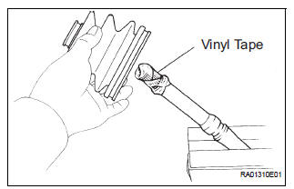
1. INSTALL REAR DRIVE SHAFT OUTBOARD JOINT BOOT
HINT: Before install the boot, wrap the spline of the outboard joint shaft with vinyl tape to prevent the boot from bearing damaged.
(a) Install new outboard joint boot, 2 outboard joint boot clamps, 2 inboard joint boot clamps and inboard joint boot.
(b) Make sure that the 2 boots are on the shaft groove.
2. INSTALL REAR DRIVE SHAFT OUTBOARD JOINT BOOT CLAMP
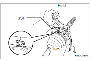
(a) Hold the drive shaft lightly in a soft vise.
(b) Install the 2 outboard joint boot clamps to the boot.
HINT: Before install the clamps, pack the outboard joint and boot with grease in the boot kit.
Grease capacity: 90 to 110 g (3.2 to 3.9 oz.)
(c) Place SST onto the 2 outboard joint boot clamps.
SST 09521-24010
(d) Tighten the SST so that the 2 outboard joint boot clamps is pinched.
NOTICE: Do not overtighten the SST.
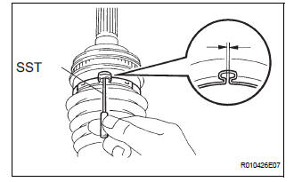
(e) Using a SST, measure the clearance of the 2 outboard joint boot clamps.
SST 09240-00020 Clearance: 1.2 to 4.0 mm (0.047 to 0.157 in.)
NOTICE: When the measured value is greater than the specified value, retighten the clamp.
3. INSTALL REAR DRIVE SHAFT INBOARD JOINT ASSEMBLY
(a) Through a new inboard joint boot, 2 new inboard joint clamps and cage.
(b) Align the matchmarks, using a brass bar and a hammer, install the inner race.
(c) Using a snap ring expander, install a new rear drive shaft snap ring.
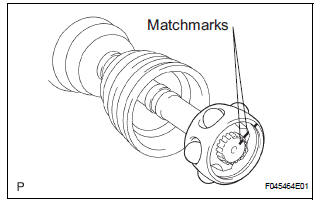
(d) Align the matchmarks, install the cage to the inner race.
(e) Install the 6 balls with grease to the inner race.
(f) Pack the inboard joint shaft and boot with grease in the boot kit.
Grease capacity: 130 to 150 g (4.6 to 5.3 oz.)

(g) Align the matchmarks, install the inboard joint assembly to the outboard joint shaft assembly.
(h) Install the clip.
4. INSTALL REAR DRIVE SHAFT INBOARD JOIN BOOT
(a) Install the inboard joint boot to the rear drive shaft inboard joint.
5. INSTALL REAR DRIVE SHAFT INBOARD JOINT BOOT CLAMP
(a) Using a screwdriver, install the No. 2 rear drive shaft inboard joint boot clamp.
(b) Install the inboard joint boot clamp by the same procedures as the No. 2 rear drive shaft inboard joint boot clamp.
 Inspection
1. INSPECT REAR DRIVE SHAFT ASSEMBLY LH
(a) Check that there is no remarkable play in the radial
direction of the outboard joint.
(b) Check that the inboard joint slides smoothly in the
thru ...
 Installation
1. INSTALL REAR DRIVE SHAFT ASSEMBLY LH
(a) Install the drive shaft to the axle carrier.
NOTICE:
Be careful not to damage the boot and ABS
speed sensor rotor to the drive shaft and oil seal
o ...
Other materials:
Master Cylinder Pressure Sensor Malfunction
DTC C1246/46 Master Cylinder Pressure Sensor Malfunction
DESCRIPTION
Master cylinder pressure sensor is connected to the skid control ECU in the
actuator.
INSPECTION PROCEDURE
1 READ VALUE ON INTELLIGENT TESTER (MASTER CYLINDER PRESSURE SENSOR)
(a) Connect the intelligent tester to the DL ...
Drive information
Items displayed can be switched
by pressing the “DISP” switch.
Current fuel economy
Displays the current rate of fuel consumption.
Use the displayed current fuel consumption as a reference.
Average fuel economy
Displays the average fuel consumption since the function was reset
...
Pre-collision seat belts (front seats of vehicles with pre-collision
system)
If the system determines that a collision is unavoidable, the front seat
belts will retract before the collision.
Emergency locking retractor (ELR)
The retractor will lock the belt during a sudden stop or on impact. It may
also
lock if you lean forward too quickly. A slow, easy motion wi ...
