Toyota Sienna Service Manual: Reassembly
1. INSTALL REAR DIFFERENTIAL PINION SHAFT
(a) Install the 2 thrust washers to the 2 side gears.
(b) Install the 2 side gears, 2 differential pinion gears, 2 differential pinion thrust washers and differential pinion shaft to the differential case.
HINT: Align the holes of the differential case and differential pinion shaft.
2. ADJUST DIFFERENTIAL PINION GEAR BACKLASH
(a) Install the side gear shaft.
(b) Measure the side gear backlash while holding 1 pinion gear toward the differential case.
Backlash: 0.05 to 0.20 mm (0.0020 to 0.0079 in.)
If the backlash is not within the specification, install the 2 side gear thrust washers of different thicknesses.
HINT:
- Measure the backlash of the side gear with the side gear shaft installed.
- Refer to the following table to select 2 thrust washers which ensures that the backlash is within the specification.
Thrust washer thickness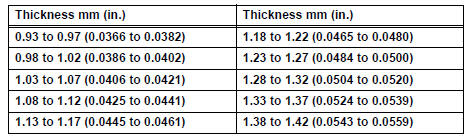
(c) Remove the side gear shaft.
(d) Using a pin punch (5 mm) and a hammer, install the straight pin through the differential case and hole of the pinion shaft.
(e) Using a chisel and a hammer, stake the outside of the differential case pin hole.
3. INSTALL DIFFERENTIAL RING GEAR
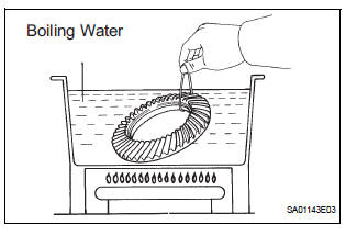
(a) Clean the contact surfaces of the differential case and ring gear.
(b) Heat the ring gear to approx. 100°C (212°F) in boiling water.
(c) Carefully take the ring gear out of the boiling water.
(d) After the moisture on the ring gear has completely evaporated, quickly install the ring gear to the differential case.
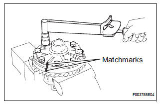
(e) Align the matchmarks on the ring gear and differential case.
(f) Temporarily install 4 new lock plates and 8 bolts.
(g) After the ring gear cools down enough, torque the 8 bolts uniformly.
Torque: 97 N*m (985 kgf*cm, 71 ft.*lbf)
HINT: Tighten the bolts, in diagonal order, a little at a time until they are all tightened.
(h) Using a chisel and a hammer, stake the 4 lock plates.
(1) Stake one claw so that it is flush against the flat surface of the bolt.
(2) As for the head so as to act as a stopper if the bolt should start to loosen.
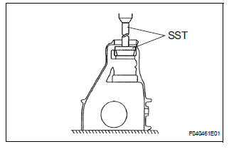
4. INSTALL REAR DIFFERENTIAL CASE BEARING RH
(a) Using SST and a press, install the case bearing (RH) to the differential case.
SST 09636-20010
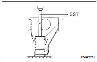
5. INSTALL REAR DIFFERENTIAL CASE BEARING LH
(a) Using SST and a press, install the case bearing (LH) to the differential case.
SST 09636-20010
6. INSPECT RUNOUT OF DIFFERENTIAL RING GEAR

(a) Install the differential case to the carrier, and install the 2 plate washers so that there is no play in the bearing.
(b) Install the 2 bearing caps with the 4 bolts Torque: 79 N*m (800 kgf*cm, 58 ft.*lbf) (c) Using a dial gage, measure the runout of the ring gear.
Maximum runout: 0.07 mm (0.0028 in.)
(d) Remove the 2 bearing caps, 2 plate washers and differential carrier.
7. INSTALL REAR DRIVE PINION FRONT TAPERED ROLLER BEARING
(a) Using SST and a press, install the front bearing (outer race) to the carrier.
SST 09950-60010 (09951-00620), 09950-70010 (09951-07150)
8. INSTALL REAR DRIVE PINION REAR TAPERED ROLLER BEARING
(a) Using SST and a press, install the rear bearing (outer race) to the carrier.
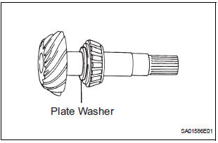
SST 09950-60020 (09951-00710), 09950-70010 (09951-07150) (b) Install the removed plate washer to the drive pinion.
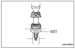
(c) Using SST and a press, install the bearing to the drive pinion.
SST 09506-30012
9. ADJUST DIFFERENTIAL DRIVE PINION PRELOAD
(a) Install the drive pinion and front bearing.
HINT: Assemble the spacer and oil seal after adjusting the gear contact pattern.
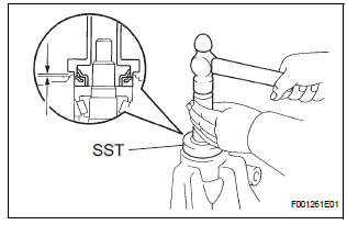
(b) Install the oil slinger, as shown in the illustration.
(c) Using SST, install the companion flange.
SST 09950-30012 (09951-03010, 09953-03010, 09954-03010, 09955-03030, 09956-03020) (d) Coat the threads of the nut with hypoid gear oil LSD.
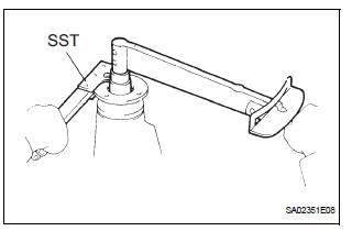
(e) Using SST to hold the flange, torque the nut.
SST 09330-00021 Torque: 108 N*m (1,100 kgf*cm, 80 ft.*lbf)
NOTICE:
- Torque the nut a little at a time, being careful not to overtighten it.
- Apply hypoid gear oil LSD to the nut.
(f) Using a torque wrench, measure the preload.
Torque: New bearing 1.1 to 1.7 N*m (1.1 to 1.7 kgf*cm, 9.6 to 14.8 in.*lbf) Reused bearing 0.6 to 0.9 N*m (6 to 9 kgf*cm, 5.2 to 7.8 in.*lbf)
10. INSTALL DIFFERENTIAL CASE ASSEMBLY
(a) Place the 2 bearing outer races on their respective bearings. Make sure the right and left races are not interchanged.
11. ADJUST DIFFERENTIAL RING GEAR BACKLASH
(a) Install the right and left bearing caps with the 4 bolts.
Torque: 79 N*m (800 kgf*cm, 58 ft.*lbf)
HINT:
- When using a new side bearing select a thrust shim which is thinner than the removed one.
- If the side bearing is reused, select a thrust shim of the same thickness as the removed one.
(b) Make sure the differential case bearing and thrust shim by tapping on the ring gear with a plastic hammer.
(c) Set the dial gauge perpendicular to the end of the ring gear face.
(d) While holding the rear drive pinion companion flange, rotate the ring gear and measure the backlash.
Backlash: 0.13 to 0.18 mm (0.0051 to 0.0071 in.)
NOTICE: Measure it at 3 points or more on the ring gear periphery.
If the measured value is out of the specified value, select a proper thrust shim so that the backlash of the differential ring gear is within the value, and install it to the ring gear back side.
Washer thickness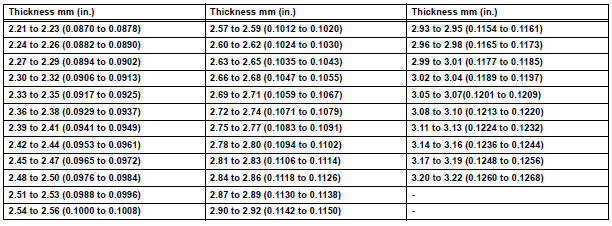
12. ADJUST TOTAL PRELOAD
(a) After adjusting the backlash of the differential ring gear, remove the teeth side thrust shim.
(b) Using a micrometer, measure the thickness of the removed thrust shim.
(c) Select a new thrust shim 0.06 to 0.09 mm (0.0024 to 0.0035 in.) which is thicker than the removed one.
HINT: Select a thrust shim whish can pressed in 2/3 rds of the way by finger.
(d) Using SST and a plastic hammer, drive in the thrust shim.
SST 09504-22011 (e) Align matchmarks on the bearing cap and differential carrier, and install the 2 bearing caps.
NOTICE: Make sure the right and left bearing caps are not interchanged.
(f) Tighten both bearing caps with the 4 bolts.
Torque: 79 N*m (800 kgf*cm, 58 ft.*lbf)
(g) Set the dial gauge to the end of the differential ring gear face.
(h) While holding the rear drive pinion companion flange, rotate the differential ring gear and measure the backlash.
Backlash: 0.13 to 0.18 mm (0.0051 to 0.0071 in.)
(i) If the measured value is out of the specified value, adjust it by increasing or decreasing the thickness of both right and left thrust shims equally.
(j) Using a torque wrench, measure the preload.
Torque: Total preload 0.3 to 0.5 N*m (3 to 5 kgf*cm, 2.6 to 4.3 in.*lbf)
13. INSPECT TOOTH CONTACT BETWEEN RING GEAR AND DRIVE PINION
(a) Coat 3 or 4 teeth at 3 different positions on the ring gear with red lead primer.
(b) Hold the companion flange firmly and rotate the ring gear in both directions.
(c) Inspection the tooth contact pattern.
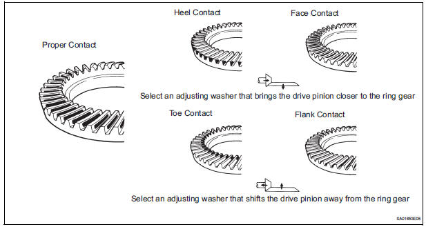
If the teeth are not contacting properly, use following table to select proper washer for correction.
Washer thickness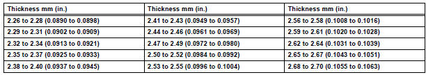
14. REMOVE REAR DRIVE PINION NUT (See page DF-18)
15. REMOVE REAR DRIVE PINION COMPANION FLANGE SUB-ASSEMBLY (See page DF-18)
16. REMOVE REAR DIFFERENTIAL DRIVE PINION OIL SLINGER
(a) Remove the rear differential drive pinion oil slinger.
17. REMOVE REAR DRIVE PINION FRONT TAPERED ROLLER BEARING (See page DF-19)
18. INSTALL REAR DIFFERENTIAL DRIVE PINION BEARING SPACER
(a) Install a new bearing spacer.
19. INSTALL REAR DRIVE PINION FRONT TAPERED ROLLER BEARING
(a) Install the rear drive pinion front tapered roller bearing to the drive pinion.
20. INSTALL REAR DIFFERENTIAL DRIVE PINION OIL SLINGER
(a) Install the oil slinger, as shown in the illustration.
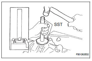
21. INSTALL REAR DIFFERENTIAL CARRIER OIL SEAL
(a) Using SST and a hammer, install a new oil seal.
SST 09554-22010 Oil seal drive in depth: 2.0+- 0.3 mm (0.079 +- 0.012 in.)
(b) Apply MP grease to the oil seal lip.
22. INSTALL REAR DIFFERENTIAL DUST DEFLECTOR
(a) Using SST and a press, install a new dust deflector.
SST 09223-00010
NOTICE: Be careful not to damage the dust deflector.
23. INSTALL REAR DRIVE PINION COMPANION FLANGE SUB-ASSEMBLY
(a) Using SST, install the companion flange to the drive pinion.
SST 09950-30012 (09951-03010, 09953-03010, 09954-03010, 09955-03030, 09956-03020)
(b) Coat the threads of a new nut with hypoid gear oil LSD.
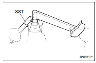
(c) Using SST to hold the flange, torque the nut.
SST 09330-00021 Torque: 108 N*m (1,100 kgf*cm, 80 ft.*lbf)
24. INSPECT DIFFERENTIAL DRIVE PINION PRELOAD
(a) Using a torque wrench, measure the preload of the drive pinon.
Torque: New bearing 1.1 to 1.7 N*m (11 to 17 kgf*cm, 9.6 to 14.8 in.*lbf) Reused bearing 0.6 to 0.9 N*m (6 to 9 kgf*cm, 5.2 to 7.8 in.*lbf)
- If the preload is greater than the specification, replace the bearing spacer
- If the preload is less than the specification, replace the nut with 13 N*m (130 kgf*cm, 9 ft.*lbf) of torque at a time until the specified preload is reached.
Torque: 235 N*m (2,400 kgf*cm, 174 ft.*lbf)
- If the torque exceeds the maximum while retightening the nut, replace the bearing spacer and repeat the preload adjusting procedure
NOTICE: Do not loosen the pinion nut to reduce the preload.
HINT: This preload is within the backlash between the drive pinion and ring gear.
25. INSPECT TOTAL PRELOAD
(a) Using a torque wrench, measure the preload.
Torque: Total preload 0.3 to 0.5 N*m (3 to 5 kgf*cm, 2.6 to 4.3 in.*lbf)
26. INSPECT DIFFERENTIAL RING GEAR BACKLASH
(a) Using a dial gauge, check the backlash of the ring gear.
Backlash: 0.13 to 0.18 mm (0.0051 to 0.0071 in.) If the backlash is not within the specification, adjust the side bearing preload or repair as necessary.
27. INSPECT REAR DRIVE PINION COMPANION FLANGE SUB-ASSEMBLY
(a) Using a dial gauge, measure the runout of the companion flange vertically.
Maximum runout: 0.10 mm (0.0039 in.)
28. INSTALL REAR DRIVE PINION NUT
(a) Using a chisel and hammer, stake the drive pinion nut.
29. INSTALL REAR DIFFERENTIAL SIDE GEAR SHAFT SEAL OIL
(a) Using SST and a hammer, install 2 new oil seals.
SST 09550-00032, 09950-70010 (09951-07200) Oil seal drive in depth: 0 +- 0.5 mm (0 +- 0.019 in.) (b) Apply MP grease to the oil seal lip.
30. INSTALL REAR DIFFERENTIAL SIDE GEAR SHAFT DUST COVER
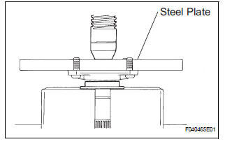
(a) Using a steel plate and a press, install a new dust cover.
NOTICE: Be careful not to damage the dust cover.
31. INSTALL REAR DIFFERENTIAL SIDE GEAR SHAFT SUB-ASSEMBLY
(a) Install the 2 side gear shaft to the differential case.
(b) Using needle nose pliers, install 2 new snap rings to the 2 side gear shafts.
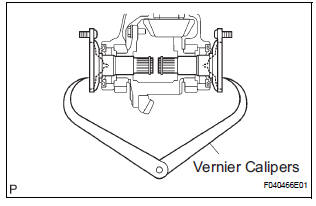
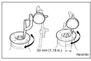
(c) Using vernier calipers, measure the distance between the right and left side gear shafts, as shown in the illustration.
Standard distance: 242 mm (9.528 in.)
32. INSTALL REAR DIFFERENTIAL CARRIER COVER
(a) Install the oil deflector and bolt to the carrier cover.
Torque: 7.4 N*m (75 kgf*cm, 65 in.*lbf) (b) Install the breather plug to the carrier cover.
Torque: 21 N*m (210 kgf*cm, 15 ft.*lbf) (c) Clean contacting surfaces of any residual FIPG material using gasoline or alcohol.
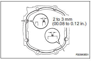
(d) Apply FIPG to the carrier.
FIPG: Toyota Genuine Seal Packing 1281, Three Bond 1281 or equivalent
HINT:
- FIPG should be applied 2 to 3 mm (0.08 to 0.12 in.) in diameter with no break.
- Allow for an overlap of 10 mm (0.37 in.) or more between the start and end of FIPG application.
- Install the carrier cover within 3 minutes after applying FIPG.
- Do not add oil or drive the vehicle immediately after installing the cover, and leave it as is for at least an hour or more. Also, for 12 hours or more, avoid rapid acceleration/deceleration.
(e) Install the carrier cover with the 8 bolts.
Torque: 47 N*m (475 kgf*cm, 34 ft.*lbf)
 Inspection
1. INSPECT RUNOUT OF DIFFERENTIAL RING GEAR
(a) Using a dial gauge , check the runout of the ring
gear.
Maximum runout:
0.07 mm (0.0028 in.)
If the runout is greater than the maximum, replace ...

Other materials:
Pre-collision seat belts (front seats of vehicles with pre-collision
system)
If the system determines that a collision is unavoidable, the front seat
belts will retract before the collision.
Emergency locking retractor (ELR)
The retractor will lock the belt during a sudden stop or on impact. It may
also
lock if you lean forward too quickly. A slow, easy motion wi ...
On-vehicle inspection
1. CHECK POWER REAR NO. 2 SEAT with STOWING FUNCTION
Check the basic functions.
Operate the fold seat switch and power rear
No.2 seat switch and check to make sure each
seat function works:
Folding-down operation
Stowing operation
Return operation
...
Selecting trailer ball
Use the correct trailer ball for your application.
Trailer ball load rating
Matches or exceeds the gross
trailer weight rating of the trailer.
Ball diameter
Matches the size of the trailer coupler.
Most couplers are stamped
with the required trailer ball size.
Shank len ...
