Toyota Sienna Service Manual: Reassembly
1. INSTALL IGNITION OR STARTER SWITCH ASSEMBLY
(a) Install the ignition or starter switch assembly to the steering column bracket assembly UPR with the 2 screws.
2. INSTALL KEY INTER LOCK SOLENOID
(a) Install the solenoid to the steering column bracket assembly with the 2 screws.
3. INSTALL UN-LOCK WARNING SWITCH ASSEMBLY
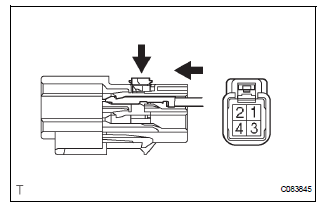
(a) Install the un-lock warning switch assembly.
(b) Connect terminals 1 and 2 of the un-lock warning switch assembly connector.
(c) Connect the un-lock warning switch assembly connector to the ignition or starter switch assembly.
4. INSTALL IGNITION SWITCH LOCK CYLINDER ASSEMBLY
(a) Make sure that the ignition switch lock cylinder assembly is in the ACC position.
(b) Install the ignition switch lock cylinder assembly.
5. INSTALL STEERING LOCK OPERATION
(a) Check that the steering lock mechanism is activated when removing the key.
(b) Check that the steering lock mechanism is deactivated when inserting the key and turning it to the ACC position
6. INSTALL STEERING COLUMN BRACKET ASSEMBLY UPPER
(a) Temporarily install the steering column upper w/ switch bracket assembly and steering column upper clamp with 2 new tapered-head bolts.
(b) Tighten the 2 tapered-head bolts until the bolt heads break off.
7. INSTALL KEY CYLINDER LIGHT ASSEMBLY (w/o Engine Immobiliser System)
8. INSTALL TRANSPONDER KEY AMPLIFIER (w/ Engine Immobiliser System)
(a) Align the transponder key amplifier with the installation position of the upper bracket with the amplifier inclined.
(b) Push the transponder key amplifier up and connect it to the upper bracket.
NOTICE: Take care not to push the amplifier up with excessive force to prevent it from being damaged.
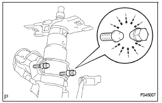
9. INSTALL STEERING INTERMEDIATE SHAFT ASSEMBLY
(a) Align the matchmarks on the steering intermediate shaft assembly and main shaft.
(b) Temporarily install the steering intermediate shaft assembly with the bolt.
Torque: 36 N*m (370 kgf*cm, 27 ft.*lbf)
 Disassembly
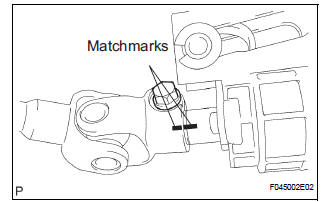
1. REMOVE STEERING INTERMEDIATE SHAFT ASSEMBLY
(a) Align the matchmarks on the steering intermediate
shaft assembly and main shaft.
(b) Remove the bolt and steering intermediate shaft
assemb ...
 Installation
1. INSTALL STEERING COLUMN ASSEMBLY
(a) Install the steering column assembly with the 3
bolts.
Torque: 25 N*m (255 kgf*cm, 18 ft.*lbf)
(b) Connect the connectors.
(c) Connect the wire har ...
Other materials:
Removal
1. PRECAUTION
CAUTION: Be sure to read "PRECAUTION" thoroughly before
servicing.
2. DISCONNECT CABLE FROM NEGATIVE BATTERY
TERMINAL
CAUTION:
Wait for 90 seconds after disconnecting the cable to
prevent the airbag working.
3. REMOVE STEERING WHEEL NO.3 COVER LOWER
Using a ...
Front Occupant Classification Sensor LH Circuit
Malfunction
DTC B1780 Front Occupant Classification Sensor LH Circuit
Malfunction
DESCRIPTION
The front occupant classification sensor LH circuit consists of the occupant
classification ECU and the
front occupant classification sensor LH.
DTC B1780 is recorded when a malfunction is detected in the fron ...
Dtc check / clear
1. DTC CHECK (USING SST CHECK WIRE)
(a) Check DTCs.
(1) Turn the ignition switch off.
(2) Using SST, connect terminals TC and CG of
DLC3.
SST 09843-18040
(3) Turn the ignition switch to the ON position.
(4) Read and record any DTCs from the tire
pressure warning light on the combin ...
