Toyota Sienna Service Manual: Reassembly
1. INSTALL COOLER DRYER
(a) Using needle nose pliers, install the cooler dryer.

(b) Install a new O-ring on the cap.
(c) Sufficiently apply compressor oil to the fitting surfaces of the O-ring and the cap.
Compressor oil: ND-OIL 8 or equivalent
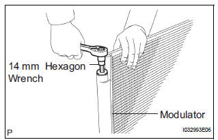
(d) Using a hexagon wrench 14 mm (0.55 in.), install the cap to the cooler condenser assembly.
Torque: 2.9 N*m (30 kgf*cm, 25 in.*lbf)
 Disassembly
1. REMOVE COOLER DRYER
(a) Using a hexagon wrench 14 mm (0.55 in.), remove
the cap from the modulator.
(b) Remove the O-ring from the cap.
(c) Using needle nose pliers, remove the cool ...
 Installation
1. INSTALL COOLER CONDENSER CORE
(a) Install the cooler condenser core with the 2 screws.
Torque: 3.9 N*m (40 kgf*cm, 35 in.*lbf)
HINT:
If the condenser is replaced with a new one, add
compress ...
Other materials:
Changing shift ranges in S mode
To enter S mode, shift the shift lever to S. Shift ranges can be selected
by operating the shift lever, allowing you to drive in the shift range of
your choosing. The shift range can be selected by the shift lever.
Upshifting
Downshifting
The selected shift range, from 1 to
6, will b ...
Precaution
1. PRECAUTION OF HEADLIGHT BULB
REPLACEMENT
When any defects such as deformation, crack, dent,
chipping, etc. are identified on the discharge
headlight (especially, on the light control ECU),
replace it with a new one.
Even if the operation seems to be normal, the failsafe
...
Removal
1. REMOVE ROOF HEADLINING ASSEMBLY
2. REMOVE SLIDING ROOF SIDE GARNISH LH
Disengage the 3 claws.
Disengage the rear clip.
Disengage the front clip.
Remove the slide garnish by pulling it rearward.
3. REMOVE SLIDING ROOF SIDE GARNISH RH
HINT:
Use the same procedures described abov ...
