Toyota Sienna Service Manual: Reassembly
1. INSTALL BACK DOOR STOPPER LOWER
- Install the 2 stoppers with the 4 bolts.
Torque: 7.0 N*m (71 kgf*cm, 62 in.*lbf)
2. INSTALL BACK DOOR BASE STOPPER BRACKET
- Install the 2 brackets with the 4 bolts.
Torque: 7.0 N*m (71 kgf*cm, 62 in.*lbf)
3. INSTALL BACK DOOR WITH MOTOR LOCK ASSEMBLY
- Install the lock with the 4 bolts.
Torque: 12.5 N*m (112 kgf*cm, 9 ft.*lbf)
- Reset the lock
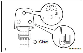
4. INSTALL POWER BACK DOOR TOUCH SENSOR LH
- Install the touch sensor with the clip.
- Using a torx driver (T25), tighten the 4 screws.
5. INSTALL POWER BACK DOOR TOUCH SENSOR RH
- Install the touch sensor with the clip.
- Using a torx driver (T25), tighten the 4 screws.
6. INSTALL BACK DOOR PULL STRAP
- Install the pull strap with the bolt.
Torque: 5.0 N*m (51 kgf*cm, 42 in.*lbf)
- Install the cover.
7. INSTALL BACK DOOR STAY BRACKET UPPER LH
- Install the bracket upper with the 2 bolts.
Torque: 12.5 N*m (112 kgf*cm, 9 ft.*lbf)
8. INSTALL POWER BACK DOOR DRIVE UNIT
- Install the drive unit with the 3 bolt.
Torque: 12.5 N*m (112 kgf*cm, 9 ft.*lbf)
- Reset the drive unit
 Adjustment
HINT:
On the RH side, use the same procedures as on the LH
side.
Since a centering bolt is used as door hinge mounting
bolts on the body side and the door side, the door cannot
be adjusted ...
 Power back door main switch
INSPECTION
1. INSPECT POWER BACK DOOR MAIN SWITCH
Inspect the resistance of the main switch.
Resistance
If the result is not as specified, replace the switch.
Apply battery voltage ...
Other materials:
Air-fuel ratio (a/f) and heated oxygen (ho2)
sensor heater monitors (front a/f and rear ho2 sensor
type)
(a) Preconditions
The monitor will not run unless:
The MIL is OFF.
(b) Drive Pattern
(1) Connect an intelligent tester to the DLC3.
(2) Turn the ignition switch to the ON position.
(3) Clear the DTCs.
(4) Start the engine.
(5) Allow the engine to idle for 10 minutes or more.
...
Warning lights
Warning lights inform the driver of malfunctions in the indicated vehicle’s
systems.
*1: These lights turn on when the engine switch is turned to the “ON”
position
(vehicles without a smart key system) or IGNITION ON mode (vehicles
with a smart key system) to indicate that a system c ...
Active Control Engine Mount System
DESCRIPTION
LOCATION
The Active Control Engine Mount (ACM) system decreases engine vibration at
engine idling using the
ACM VSV. The VSV is controlled by a pulse signal transmitted to the VSV from the
ECM. The frequency
of this pulse signal is matched to the engine speed to decrease engi ...
