Toyota Sienna Service Manual: Reassembly
1. INSTALL OVERDRIVE DIRECT CLUTCH O-RING
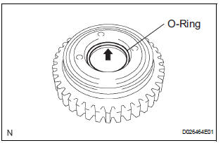
(a) Coat an O-ring with ATF, and install it to the direct clutch drum.
NOTICE: Make sure that the O-ring is not twisted or pinched when it is installed.
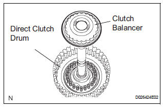
2. INSTALL OVERDRIVE DIRECT CLUTCH DRUM SUBASSEMBLY
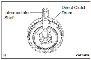
(a) Coat the direct clutch drum with ATF, and install it to the intermediate shaft.
NOTICE:
- Be careful not to damage the O-ring.
- Be careful not to damage the lip of the direct clutch drum.
3. INSTALL OVERDRIVE DIRECT CLUTCH PISTON
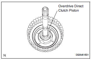
(a) Coat the overdrive direct clutch piston with ATF, and install it to the direct clutch drum.
4. INSTALL OVERDRIVE CLUTCH RETURN SPRING SUB-ASSEMBLY
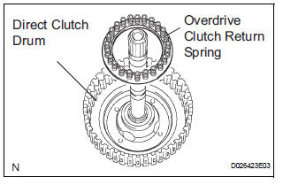
(a) Install the overdrive clutch return spring to the direct clutch drum.
NOTICE: Installing the spring sub-assembly, check that all of the springs are fit in piston correctly.
(b) Coat the clutch balancer with ATF.
(c) Install the clutch balancer to the direct clutch drum.
NOTICE:
- Be careful not to damage the lip of the direct clutch balancer.
- Make sure that the lip of the seal is not pinched and that it has no other defects.
- Apply sufficient ATF to the sealing lip before installing the clutch balancer.
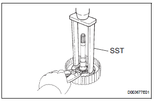
(d) Place SST on the clutch balancer and compress the overdrive clutch return spring with a press.
SST 09387-00020
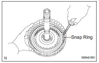
(e) Using a snap ring expander, install the snap ring to the direct clutch drum.
(f) Be sure that the end gap of the snap ring is not aligned with the spring retainer claw.
NOTICE:
- Stop the press when the spring seat is lowered to the place 1 to 2 mm (0.039 to 0.078 in.) from the snap ring groove.
- This prevents the spring seat from being deformed.
- Do not expand the snap ring excessively.
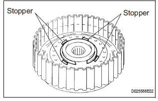
(g) Set the end gap of the snap ring in the piston shown in the illustration.
NOTICE: The end gap of the snap ring should not align with any of the stoppers.
5. INSTALL OVERDRIVE DIRECT CLUTCH DISC
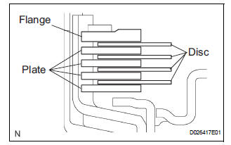
(a) Coat the 4 discs with ATF.
(b) Install the 4 plates, 4 discs and flange to the intermediate shaft.
NOTICE: Make sure that the plates, discs, and flange are installed as shown in the illustration.
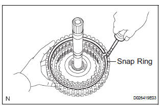
(c) Using a screwdriver, install the snap ring.
(d) Check that the end gap of the snap ring is not aligned with one of the cutouts.
NOTICE: The snap ring should be fully engaged in the groove of the drum.
6. INSTALL DIRECT MULTIPLE DISC CLUTCH DISC
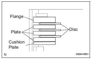
(a) Coat the 3 disc with ATF.
(b) Install the cushion plate, 3 plates, 3 disc and flange to the intermediate shaft.
NOTICE:
- Install the cushion plate with the mark on the white surface facing to plate.
- Be careful about the order of discs, plate and flange assembly.
(c) Using a screwdriver, install the snap ling.
(d) Check that the end gap of the snap ling is not aligned with one of the cutouts.
NOTICE: The slap ring should be fixed certainly in the groove of the drum.
 Inspection
1. Inspect pack clearance of reverse clutch
(A) install the intermediate shaft and needle roller
bearing onto the transaxle rear cover.
(B) using a dial indicator, measure the reverse clutch
...
Other materials:
Initialization
1. RESET
When the control motor and clutch is replaced:
The power slide door ECU cannot receive a switch
signal from the control motor and clutch. This may
cause the power slide door system to enter fail-safe
mode and DTC (B2224 (LH) or B2223 (RH)) to set,
and also make the syste ...
Dtc check / clear
1. DTC CHECK (NORMAL MODE)
NOTICE:
When the diagnostic system is switched from the
normal mode to the check mode, all the DTCs and
freeze frame data recorded in the normal mode will
be erased. So before switching modes, always check
the DTCs and freeze frame data, and note the ...
Magnetic clutch relay
ON-VEHICLE INSPECTION
1. INSPECT MAGNETIC CLUTCH RELAY
(a) Remove the magnetic clutch relay.
(b) Measure the resistance according to the value(s) in
the table below.
Standard resistance
If the resistance is not as specified, replace the
magnetic clutch relay. ...
