Toyota Sienna Service Manual: Removal
HINT: Replace the RH side by the same procedures as the LH side.
1. REMOVE REAR WHEEL
2. REMOVE REAR DISC BRAKE CALIPER ASSEMBLY LH
(a) Removing the 2 bolts, separate the rear disc brake caliper assembly LH for disc rear brake type.
NOTICE: Using a string and so on, hang down the disc brake caliper.
3. REMOVE REAR DISC
(a) Remove rear disc for disc rear brake type.
4. REMOVE REAR BRAKE DRUM SUB-ASSEMBLY
(a) Remove rear brake drum sub-assembly for drum rear brake type.
5. SEPARATE SKID CONTROL SENSOR WIRE
(a) Disconnect the connector
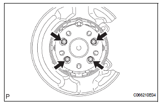
6. REMOVE REAR AXLE HUB & BEARING ASSEMBLY LH

(a) Remove the 4 bolts and hub & bearing assembly LH.
 On-vehicle inspection
1. INSPECT REAR AXLE HUB BEARING BACKLASH
(a) Using a dial gauge, check for backlash near the
center of the axle hub.
Maximum:
0.05 mm (0.0020 in.)
If backlash exceeds the maximum, replace th ...
 Installation
1. INSTALL REAR AXLE HUB & BEARING ASSEMBLY LH
(a) Install the hub & Bearing assembly LH with the 4
bolts.
Torque: 56 N*m (571 kgf*cm, 41 ft.*lbf)
2. INSPECT BEARING BACKLASH (See page ...
Other materials:
Transmitter battery
REPLACEMENT
1. REMOVE TRANSMITTER BATTERY
NOTICE:
Special caution should be taken for handling each
component as they are precision electronic
components.
Using a coin or the equivalent, pry out the
transmitter case.
NOTICE:
Do not forcibly pry out the case.
Re ...
Brake System Malfunction
DTC P1578 Brake System Malfunction
DESCRIPTION
This DTC is output when the VSC system has a problem. Check the VSC system
when this DTC is
output
DTC No.
DTC Detection Condition
Trouble Area
P1578
The ECM receives a brake system error signal for 0.2
...
Inspection
1. INSPECT GARAGE DOOR OPENER
Press the switch and check that each red LED turns
on. If one or more of the switches does not turn on
the LED, confirm normal operation of the fuse and
wire harness, then replace the garage door opener.
2. INSPECT GARAGE DOOR OPENER REGISTRATION ...
