Toyota Sienna Service Manual: Removal
1. REMOVE REAR WHEEL
2. REMOVE SKID CONTROL SENSOR WIRE (for 2WD)
(a) Disconnect the skid control sensor connector.
(b) Remove the bolt and disconnect the bracket from the rear axle beam assembly.
HINT: Separate the RH side by the same procedures as the LH side.
3. SEPARATE SPEED SENSOR REAR LH (for 4WD)
(a) Remove the bolt and speed sensor rear LH.
4. SEPARATE SPEED SENSOR REAR RH (for 4WD)
HINT: Separate the RH side by the same procedures as the LH side.
5. REMOVE EXHAUST PIPE ASSEMBLY TAIL
HINT:
- 2WD DRIVE TYPE (See page EX-2)
- 4WD DRIVE TYPE (See page EX-8)
6. REMOVE PROPELLER W/CENTER BEARING SHAFT ASSEMBLY (for 4WD)
HINT: (See page PR-2)
7. SEPARATE REAR DRIVE SHAFT ASSEMBLY LH (for 4WD)
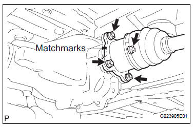
(a) Place matchmarks on the rear drive shaft assembly LH and differential flange.
(b) Remove the 4 nuts and 4 washers, separate rear drive shaft assembly LH.
8. SEPARATE REAR DRIVE SHAFT ASSEMBLY RH (for 4WD)
HINT: Separate the RH side by the same procedures as the LH side.
9. REMOVE DIFFERENTIAL CARRIER ASSEMBLY REAR (for 4WD)
HINT: (See page DF-8)
10. SEPARATE PARKING BRAKE CABLE ASSEMBLY NO.3
(a) Remove the 2 bolts and parking brake cable assembly No.3.
11. SEPARATE PARKING BRAKE CABLE ASSEMBLY NO.2
HINT: Separate the RH side by the same procedures as the LH side.
12. SEPARATE REAR BRAKE TUBE NO.2
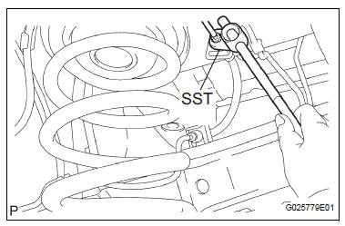
(a) Using SST, separate the brake tube from the flexible hose. Catch the brake fluid with a container as it drains out.
SST 09023-00101
(b) Remove the clip, and separate the flexible hose.
(c) Remove the bolt and separate the brake tube from rear axle beam assembly.
13. SEPARATE REAR BRAKE TUBE NO.1
SST 09023-00101
HINT: Separate the RH side by the same procedures as the LH side.
14. REMOVE FUEL TANK FILLER HOSE COVER
(a) Remove the 2 bolts, 3 screws, 3 nuts and fuel tank filler pipe protector.
(b) Remove the 3 bolts and fuel tank filler hose cover.
15. REMOVE REAR FLOOR NO.2 CROSSMEMBER BRACE LH
(a) Remove the 2 bolts and floor No.2 crossmember brace.
16. REMOVE REAR FLOOR NO.2 CROSSMEMBER BRACE RH
HINT: Remove the RH side by the same procedures as the LH side.
17. LOOSEN REAR AXLE BEAM ASSEMBLY
(a) Refer to hint below.
HINT: Loosen the RH side by the same procedures as the LH side.
NOTICE:
- When loosening the bolt, hold the nut not to rotate.
- Do not remove the bolt and nut.
18. SEPARATE SHOCK ABSORBER ASSEMBLY REAR LH
(a) Support the rear axle beam assembly with a jack.
(b) Remove the bolt and separate the shock absorber assembly rear LH.
19. SEPARATE SHOCK ABSORBER ASSEMBLY REAR RH
HINT: Separate the RH side by the same procedures as the LH side.
20. REMOVE COIL SPRING REAR LH
(a) Apply a shop rug between the coil spring rear LH and rear axle beam assembly.
(b) Apply a shop rug between the coil spring rear RH and rear axle beam assembly.
(c) Remove the coil spring LH by slowly lowering the jack.
21. REMOVE REAR COIL SPRING INSULATOR UPPER LH
(a) Remove the rear coil spring insulator upper LH from the coil spring rear LH.
 Rear coil spring
COMPONENTS
...
 Installation
1. INSTALL REAR COIL SPRING INSULATOR UPPER LH
(a) Install the insulator upper LH to the coil spring rear
LH.
2. INSTALL COIL SPRING REAR LH
(a) Apply a shop rug to the rear axle beam asse ...
Other materials:
Short in Front Pretensioner Squib LH Circuit
DTC B0135/73 Short in Front Pretensioner Squib LH Circuit
DESCRIPTION
The front pretensioner squib LH circuit consists of the center airbag sensor
assembly and the front seat
outer belt assembly LH.
This circuit instructs the SRS to deploy when deployment conditions are met.
DTC B0135/73 ...
Things you should know
If you notice any symptoms
If you notice any of the following symptoms, refer to the likely cause
and the solution, and re-check.
If the symptom is not resolved by the solution, have the vehicle
inspected by your Toyota dealer.
Likely cause
Solution
The ima ...
Inspection
1. INSPECT LOCK PLATE FOR DAMAGE
(a) Inspect the lock plate for damage.
HINT:
Reassembly of a deformed tank will be
impossible. Therefore, first correct the shape of
the lock plate groove with pliers or a similar tool,
if necessary.
Water leakage will result if the bottom of the lo ...
