Toyota Sienna Service Manual: Removal
HINT:
- Don't use the dropped or damaged yawrate sensor
- Free from the foreign matters between yaerate sensor bracket and body.
- Make sure the sensor direction.
1. REMOVE FRONT SEAT ASSEMBLY RH
HINT: See page SE-40.
2. REMOVE FRONT DOOR SCUFF PLATE RH
3. REMOVE COWL SIDE TRIM BOARD RH
(a) Remove the nut and cowl side trim board plate RH.
4. REMOVE YAW RATE AND DECELERATION SENSOR
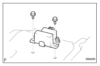
(a) Disconnect the yawrate sensor connector.
(b) Remove the 2 bolts and yawrate sensor.
 Yaw rate and deceleration sensor
Components
...
 Installation
1. INSTALL YAW RATE AND DECELERATION SENSOR
(a) Connect the yawrate sensor connector.
(b) Install the yawrate sensor with the 2 bolts.
Torque: 13 N*m (136 kgf*cm, 10 ft.*lbf)
2. INSTALL COWL ...
Other materials:
Removal
1. REMOVE REAR DOOR SCUFF PLATE LH
2. REMOVE REAR DOOR WEATHERSTRIP LH
3. REMOVE BACK DOOR WEATHERSTRIP
4. REMOVE BACK DOOR SCUFF PLATE
5. REMOVE QUARTER TRIM FRONT PANEL ASSEMBLY LH
6. REMOVE VOLTAGE INVERTER ASSEMBLY
Disconnect the connector.
Remove the 2 bolts and the v ...
Camshaft Position "B" Actuator Circuit
DESCRIPTION
The Variable Valve Timing (VVT) system includes the ECM, OCV and VVT
controller. The ECM sends a
target duty-cycle control signal to the OCV. This control signal regulates the
oil pressure supplied to the
VVT controller. Camshaft timing control is performed according to engine ...
Inspection procedure
1 BASIC INSPECTION
Check the conditions necessary for the power slide door
to open:
Power slide door main switch is in the ON position
(switch free: orange paint on the top of the switch
appears).
Slide door is unlocked (door lock position switch is
in the ON position when ...
