Toyota Sienna Service Manual: Removal
HINT: For the parking brake cable assembly No. 2, perform the same procedure to the parking brake cable assembly No. 3.
1. REMOVE REAR WHEEL
2. REMOVE REAR BRAKE DRUM SUB-ASSEMBLY (for Drum Type) (See page BR-37)
3. REMOVE FRONT BRAKE SHOE (for Drum Type) (See page BR-37)
4. REMOVE REAR BRAKE SHOE (for Drum Type) (See page BR-38)
5. SEPARATE REAR DISC BRAKE CALIPER ASSEMBLY LH (for Disc Type) (See page PB-15)
6. REMOVE REAR DISC (for Disc Type) (See page BR- 32)
7. REMOVE PARKING BRAKE SHOE ASSEMBLY LH NO.1 (for Disc Type) (See page PB-15)
8. REMOVE PARKING BRAKE SHOE ADJUSTING SCREW SET (for Disc Type)
9. REMOVE PARKING BRAKE SHOE STRUT LH (for Disc Type)
10. REMOVE PARKING BRAKE SHOE ASSEMBLY LH NO.2 (for Disc Type) (See page PB-15)
11. SEPARATE PARKING BRAKE CABLE ASSEMBLY NO.3
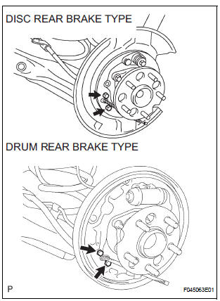
(a) Remove the 2 bolts, and disconnect the parking brake cable No. 3 from the backing plate.
12. REMOVE PARKING BRAKE CABLE ASSEMBLY NO.3
(a) Remove the 3 bolts and the button to disconnect the parking brake cable No. 3 from the body.
(b) Disconnect the parking brake cable No. 3 from the parking brake equalizer, and remove the parking brake cable No. 3.
(c) Remove the parking brake cable LH guide from the parking brake cable assembly No. 3.
 Parking brake cable
Components
...
 Installation
1. INSTALL PARKING BRAKE CABLE ASSEMBLY NO.3
(a) Install the parking brake cable LH guide to the
parking brake cable assembly No. 3.
(b) Connect the parking brake cable No. 3 to the
parking brak ...
Other materials:
Changing shift ranges in S mode
To enter S mode, shift the shift lever to S. Shift ranges can be selected
by operating the shift lever, allowing you to drive in the shift range of
your choosing. The shift range can be selected by the shift lever.
Upshifting
Downshifting
The selected shift range, from 1 to
6, will b ...
Fuel information
You must only use unleaded gasoline in your vehicle.
Select octane rating 87 (Research Octane Number 91) or higher.
Use of unleaded gasoline with an octane rating lower than 87
may result in engine knocking. Persistent knocking can lead to
engine damage.
At minimum, the gasoline you use s ...
Transfer system
PRECAUTION
NOTICE:
1. Before disassembly, clean the transfer assembly of
any sand or mud to prevent it from entering inside the
transfer during disassembly and assembly.
2. When removing any light alloy part such as a transfer
cover, do not pry it off with a tool like a screwdriver,
but tap ...
