Toyota Sienna Service Manual: Removal
1. PRECAUTION
HINT: See page RS-1
2. DISCONNECT BATTERY NEGATIVE TERMINAL
Wait for 90 seconds after disconnecting the battery terminal to prevent the airbag working.
3. PLACE FRONT WHEELS FACING STRAIGHT AHEAD
4. REMOVE STEERING WHEEL COVER LOWER NO.2 (See page RS-424)
5. REMOVE STEERING WHEEL COVER LOWER NO.3 (See page RS-424)
6. REMOVE HORN BUTTON ASSEMBLY (See page RS- 424)
7. REMOVE STEERING WHEEL ASSEMBLY
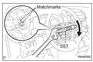
(a) Remove the steering wheel assembly set nut.
(b) Put matchmarks on the steering wheel assembly and main shaft assembly.
(c) Using SST, remove the steering wheel assembly.
SST 09950-50013 (09951-05010, 09952-05010, 09953-05020, 09954-05021)
8. REMOVE STEERING COLUMN COVER
(a) Remove the 2 screws and steering column cover.
9. REMOVE SPIRAL CABLE SUB-ASSEMBLY (See page RS-434)
10. REMOVE HEADLIGHT DIMMER SWITCH ASSEMBLY (See page LI-102)
11. REMOVE WINDSHIELD WIPER SWITCH ASSEMBLY (See page WW-17)
12. REMOVE FRONT DOOR SCUFF PLATE LH
13. REMOVE COWL SIDE TRIM BOARD LH
14. REMOVE INSTRUMENT PANEL FINISH PANEL SUBASSEMBLY LOWER LH (See page IP-6)
15. REMOVE INSTRUMENT PANEL SAFETY PAD INSERT SUB-ASSEMBLY NO.1 (See page IP-6)
16. REMOVE HEATER TO FOOT DUCT NO.3
(a) Disengage the 3 claws and remove the sir duct No.
3.
17. SEPARATE STEERING INTERMEDIATE SHAFT ASSEMBLY
(a) Loosen the bolt.
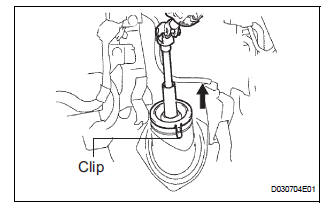
(b) Release the 3 clips and separate the dust cover.
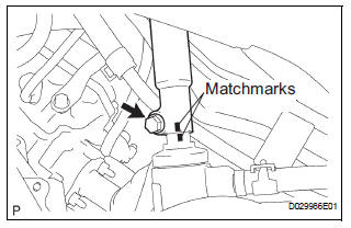
(c) Align the matchmarks on the steering intermediate shaft assembly and steering gear assembly.
(d) Remove the bolt and separate the steering intermediate shaft assembly.
18. REMOVE STEERING COLUMN ASSEMBLY
(a) Disconnect the connectors and wire harness clamps.
(b) Remove the 3 bolts and steering column assembly from the instrument panel reinforcement assembly.
 Steering Column Assembly
COMPONENTS
...
 Disassembly
1. REMOVE STEERING INTERMEDIATE SHAFT ASSEMBLY
(a) Align the matchmarks on the steering intermediate
shaft assembly and main shaft.
(b) Remove the bolt and steering intermediate shaft
assemb ...
Other materials:
Problem symptoms table
WINDOW DEFOGGER SYSTEM
Symptom
Suspected area
w/ Deicer: Front window deicer does not operate.
(indicator light ON)
FR DEF fuse
Front window deicer relay
Front window deicer wire
Wire harness
w/ deicer: Front window deicer ...
Short in Rear Curtain Shield Squib LH Circuit
DTC B1635/87 Short in Rear Curtain Shield Squib LH Circuit
DESCRIPTION
The rear curtain shield squib LH circuit consists of the center airbag sensor
assembly and the curtain
shield airbag assembly LH.
The circuit instructs the SRS to deploy when deployment conditions are met.
DTC B1635/87 ...
If the shift lever cannot
be shifted from P
If the shift lever cannot be shifted with your foot on the brake
pedal, there may be a problem with the shift lock system (a system
to prevent accidental operation of the shift lever). Have the
vehicle inspected by your Toyota dealer immediately.
The following steps may be used as an emergency ...
