Toyota Sienna Service Manual: Removal
1. DRAIN POWER STEERING FLUID
2. REMOVE FRONT WHEEL RH
3. REMOVE FRONT FENDER APRON SEAL RH (See page EM-26)
4. REMOVE FAN AND GENERATOR V BELT (See page EM-6)
5. DISCONNECT NO. 1 FLUID RESERVOIR TO PUMP HOSE
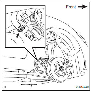
(a) Slide the clip and disconnect the No. 1 fluid reservoir to pump hose from the vane pump assembly.
6. DISCONNECT PRESSURE FEED TUBE ASSEMBLY
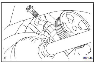
(a) Remove the union bolt and disconnect the pressure feed tube assembly from the vane pump assembly.
(b) Remove the gasket from the pressure feed tube assembly.
7. DISCONNECT POWER STEERING FLUID PRESSURE SWITCH CONNECTOR
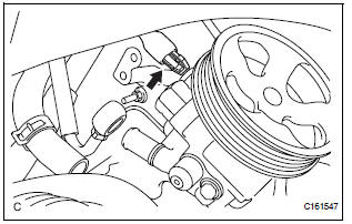
(a) Disconnect the power steering fluid pressure switch connector.
8. REMOVE VANE PUMP ASSEMBLY
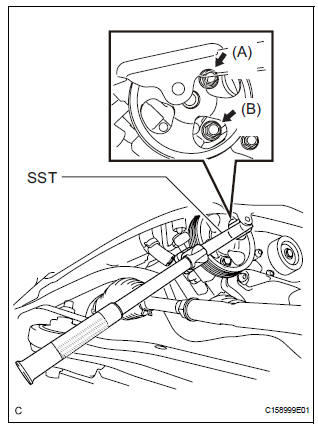
(a) Using SST, loosen bolt (A) and remove bolt (B), and then remove the vane pump assembly.
SST 09249-63010
(b) Remove the bolt from the vane pump assembly.
 Vane pump
COMPONENTS
...
 Disassembly
1. HOLD VANE PUMP ASSEMBLY
(a) Using SST, hold the vane pump assembly in a vise.
SST 09630-00014 (09631-00132)
2. REMOVE POWER STEERING SUCTION PORT UNION
(a) Remove the bolt and the pow ...
Other materials:
On-vehicle inspection
1. INSPECT FRONT PASSENGER AIRBAG ASSEMBLY
(VEHICLE NOT INVOLVED IN COLLISION)
Perform a diagnostic system check.
With the front passenger airbag assembly installed
on the vehicle, perform a visual check. If there are
any defects as mentioned below, replace the
instrumen ...
Symptom confirmation and diagnostic trouble code
HINT:
The diagnostic system in the SIENNA has various
functions.
The first function is the Diagnostic Trouble Code
(DTC) check. A DTC is a code stored in the ECU
memory whenever a malfunction in the signal circuits
to the ECU occurs. In a DTC check, a previous
malfunction's DTC can be ...
Diagnosis system
1. CHECK DLC3
The vehicle's ECU uses ISO 15765-4 for
communication protocol. The terminal arrangement
of the DLC3 complies with SAE J1962 and matches
the ISO 15765-4 format.
NOTICE:
*: Before measuring the resistance, leave the
vehicle as is for at least 1 minute and do not
ope ...
