Toyota Sienna Service Manual: Removal
1. REMOVE INSTRUMENT PANEL SUB-ASSEMBLY WITH PASSENGER AIRBAG ASSEMBLY
HINT: Refer to the instructions for removal of the instrument panel sub-assembly w/ passenger airbag assembly (See page IP-5).
2. REMOVE HEATER TO FOOT DUCT NO.1
(a) Remove the clip and the heater to foot duct No. 1.
3. REMOVE STEREO COMPONENT AMPLIFIER ASSEMBLY (w/ Stereo Compartment Amplifier) (See page AV-173)
4. REMOVE ECM (See page ES-498)
5. REMOVE BLOWER ASSEMBLY
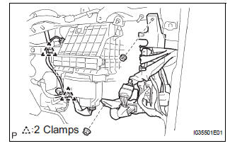
(a) Release the 2 clamps, the 2 nuts and the wire harness.
(b) Remove the bolt, the 2 screws and the nut.
(c) Remove the blower assembly.
 Blower unit
COMPONENTS
...
 Disassembly
1. REMOVE AIR REFINER ELEMENT
(a) Release the 2 claw fittings and remove the air filter
sub-assembly.
(b) Remove the air refiner element from the air filter
cover plate.
2. REMOVE COOLING ...
Other materials:
Inspection
1. INSPECT REAR SPEED SENSOR
(a) Remove the seat cushion and seatback.
(b) Disconnect the speed sensor connector.
(c) Measure the resistance between terminals 1 and 2
of the speed sensor connector
OK:
Resistance:
1.1 +- 0.2 kΩ at 25 +- 5 °C
(d) Measure the resistance between ea ...
Removal
1. REMOVE BACK DOOR CENTER GARNISH (See page
ET-18)
2. REMOVE POWER BACK DOOR ROD (See page ED-
220)
3. REMOVE BACK DOOR LH SIDE GARNISH
4. REMOVE BACK DOOR RH SIDE GARNISH
5. REMOVE BACK DOOR PULL STRAP (See page ED-
221)
6. REMOVE BACK DOOR TRIM BOARD ASSEMBLY
7. REMOVE LH BACK-UP LIGH ...
Power Source Circuit
DESCRIPTION
This is the power source circuit for the outer mirror control ECU.
WIRING DIAGRAM
INSPECTION PROCEDURE
1 INSPECT OUTER MIRROR CONTROL ECU (POWER SOURCE)
Disconnect the O9 or O11 ECU connector.
Measure the voltage and resistance according to the
value(s) in the t ...
