Toyota Sienna Service Manual: Removal
1. DISCHARGE REFRIGERANT FROM REFRIGERATION SYSTEM
SST 07110-58060 (07117-58080, 07117-58090, 07117-78050, 07117-88060, 07117-88070, 07117-88080)
HINT: See page AC-172.
2. REMOVE REAR DOOR SCUFF PLATE RH (See page IR-7)
3. REMOVE BACK DOOR SCUFF PLATE (See page IR- 8)
4. REMOVE QUARTER TRIM PANEL ASSEMBLY FRONT RH (See page IR-9)
5. REMOVE ROOF HEADLINING GARNISH REAR (See page IR-9)
6. REMOVE RR WINDOW SIDE GARNISH ASSEMBLY NO.2 RH (See page IR-9)
7. REMOVE AIR DUCT ASSEMBLY
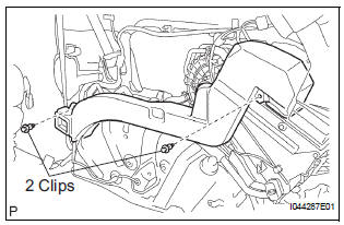
(a) Remove the 2 clips and the air duct assembly from the air conditioning blower assembly.
8. REMOVE COVER SUB-ASSEMBLY
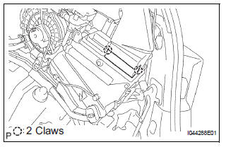
(a) Disengage the 2 claw fittings and remove the cover sub-assembly.
9. REMOVE AIR DUCT ASSEMBLY

(a) Remove the air duct assembly.
10. DISCONNECT HEATER HOSE
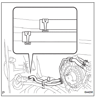
(a) Release the claw fittings and release the heater hose clamp.
(b) Using pliers, grip the claws of the 2 clips and slide the clip to disconnect the 2 heater hoses.
11. DISCONNECT AIR CONDITIONING TUBE AND ACCESSORY ASSEMBLY
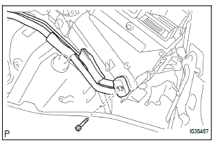
(a) Remove the 2 bolts and disconnect the air conditioning tube & accessory assembly.
12. REMOVE AIR CONDITIONING BLOWER ASSEMBLY
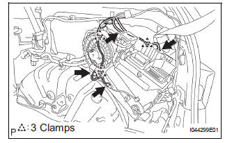
(a) Disconnect the 4 connectors, release the 3 clamps and separate the wire harness.
(b) Remove the 3 bolts and the air conditioning blower assembly.
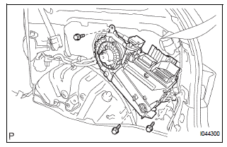
 Blower unit (for rear air conditioning system)
COMPONENTS
...
 Disassembly
1. REMOVE COOLER THERMISTOR NO.1 (for Automatic Air Conditioning System)
(a) Disengage the 2 claw fittings and the clamp and
remove the cooler thermistor No. 1.
2. REMOVE COOLING UNIT MOTOR SUB ...
Other materials:
Inspection
1. INSPECT MULTIPLE DISC CLUTCH HUB
(a) Using a dial indicator, measure the inside diameter
of the forward clutch hub bushing
Standard inside diameter:
23.025 to 23.046 mm (0.9065 to 0.9073 in.)
Maximum inside diameter:
23.09 mm (0.9091 in.)
NOTICE:
Check the contact surface of ...
Reassembly
1. INSTALL COOLER DRYER
(a) Using needle nose pliers, install the cooler dryer.
(b) Install a new O-ring on the cap.
(c) Sufficiently apply compressor oil to the fitting
surfaces of the O-ring and the cap.
Compressor oil:
ND-OIL 8 or equivalent
(d) Using a hexagon wrench 14 mm ( ...
DVD-ROM Abnormal
DTC 44-43 DVD-ROM Abnormal
DESCRIPTION
DTC No.
DTC Detecting Condition
Trouble Area
44-43
DVD-ROM operation is abnormal.
DVD
Television display assembly
INSPECTION PROCEDURE
HINT:
After the inspection is completed, clear the ...
