Toyota Sienna Service Manual: Removal
1. REMOVE REAR DOOR SCUFF PLATE
2. REMOVE REAR DOOR WEATHERSTRIP
3. REMOVE BACK DOOR WEATHERSTRIP
4. REMOVE BACK DOOR SCUFF PLATE
5. REMOVE FRONT QUARTER TRIM PANEL ASSEMBLY
- Remove the floor anchor cover.
- Remove the bolt and disconnect the No. 2 rear seat outer belt assembly on the floor anchor side.
- Remove the 2 package holder net hooks.
- Using a screwdriver, disengage the claw and remove the courtesy light.
- Disconnect the courtesy light connectors.
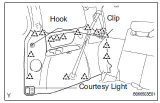
- Using a screwdriver, disengage the 16 clips and remove the quarter trim panel assembly.
HINT: Tape the screwdriver tip before use.
6. REMOVE REAR WINDOW SIDE GARNISH ASSEMBLY
7. REMOVE NO. 1 REAR SEAT OUTER BELT ASSEMBLY (for 7-Passenger)
HINT: Refer to the instructions for disassembly of the rear No. 1 seat assembly (for captain seat type).
- Remove the rear seatback board RH.
- Remove the rear seat shoulder belt cover.
- Remove the bolt, nut and No. 1 rear seat outer belt assembly.
8. REMOVE 3 POINT TYPE REAR SEAT BELT ASSEMBLY (for 8-Passenger)
- Remove the nut and disconnect the 3 point type rear seat belt on the shoulder anchor side.
9. REMOVE NO. 2 REAR SEAT OUTER BELT ASSEMBLY
- Using a screwdriver, disengage the 2 claws and
remove the cover of the No. 2 rear seat outer belt
assembly on the shoulder anchor side.
HINT: Tape the screwdriver tip before use.
- Remove the bolt and disconnect the No. 2 rear seat outer belt assembly on the shoulder anchor side.
- Remove the bolt on the retractor side and remove the No. 2 rear seat outer belt assembly.
 Rear seat outer belt assembly
COMPONENTS
...
 Installation
1. INSTALL NO. 2 REAR SEAT OUTER BELT ASSEMBLY
NOTICE:
Do not disassemble the retractor.
Check the degree of tilt when the No. 2 rear seat
outer belt assembly begins to lock the ELR. ...
Other materials:
Removal
1. PRECAUTION
CAUTION:
Be sure to read "PRECAUTION" thoroughly before servicing.
2. DISCONNECT CABLE FROM NEGATIVE BATTERY
TERMINAL
CAUTION:
Wait for 90 seconds after disconnecting the cable to
prevent the airbag working.
3. REMOVE FRONT SEAT ASSEMBLY (for Manual Seat)
4. REMOVE F ...
For vehicles equipped with traction control (trac) system
When using a 2-wheel drum tester such as a
speedometer tester or chassis dynamometer, etc., or
jacking up the front wheels and driving the wheels,
always push in the TRAC cut ("TRAC OFF") switch and
turn the TRAC system OFF.
FOR VEHICLES EQUIPPED WITH TRACTION CONTROL (TRAC) SYS ...
Installing child restraints
Follow the child restraint system manufacturer’s instructions.
Firmly secure child restraints to the rear seats using the LATCH
anchors or a seat belt. Attach the top tether strap when installing
a child restraint.
The lap/shoulder belt can be used if your child restraint sy ...
