Toyota Sienna Service Manual: Removal
1. REMOVE INSTRUMENT PANEL SAFETY PAD SUBASSEMBLY
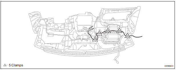
2. REMOVE ANTENNA CORD SUB-ASSEMBLY
- Replace the 5 clamps and remove the antenna cord sub-assembly.
3. REMOVE PULL TOP ANTENNA POLE SUBASSEMBLY
4. REMOVE ANTENNA ORNAMENT
- Remove the antenna ornament.
5. REMOVE ANTENNA ASSEMBLY WITH HOLDER
- Disconnect the connector and remove the bolt.
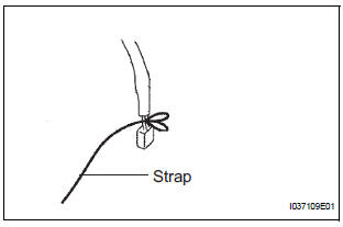
- Tie the string at the tip of the cable of the antenna assembly with holder.
HINT: Leave the string in the vehicle. It will be used when installing the antenna assembly with holder.

- Remove the nut and the antenna assembly with holder.
6. REMOVE ROOF HEADLINING ASSEMBLY
7. REMOVE AMPLIFIER ANTENNA ASSEMBLY
- Disconnect the connectors.
- Remove the 3 bolts.
- Disengage the 16 clamps and remove the amplifier antenna assembly.
 Radio antenna cord
COMPONENTS
...
 Installation
1. INSTALL AMPLIFIER ANTENNA ASSEMBLY
Engage the 16 clamps to install the amplifier
antenna assembly.
Install the 3 bolts.
Connect the connectors.
2. INSTALL ROOF HEAD ...
Other materials:
Headlight Relay Circuit
DESCRIPTION
The Multiplex network body ECU controls HEAD relay when signal is received
from headlight dimmer
switch assembly.
WIRING DIAGRAM
INSPECTION PROCEDURE
1 PERFORM ACTIVE TEST BY INTELLIGENT TESTER
Connect the intelligent tester to DLC3.
Turn the ignition switch ON and ...
SRS Warning Light Remains ON
DESCRIPTION
The SRS warning light is located on the combination meter assembly.
When the SRS is normal, the SRS warning light comes on for approximately 6
seconds after the ignition
switch is turned from the LOCK position to ON position, and then goes off
automatically.
If there is a mal ...
Disassembly
1. INSPECT UNDERDRIVE PACK CLEARANCE
HINT:
(See page AX-262)
2. REMOVE UNDERDRIVE CLUTCH FLANGE NO.2 HOLE
SNAP RING
a) Using a screwdriver, remove the underdrive clutch
flange No.2 snap ring.
3. REMOVE UNDERDRIVE CLUTCH DISC NO.1
(a) Remove the flange, 4 discs and 4 plates from the
...
