Toyota Sienna Service Manual: Removal
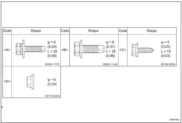
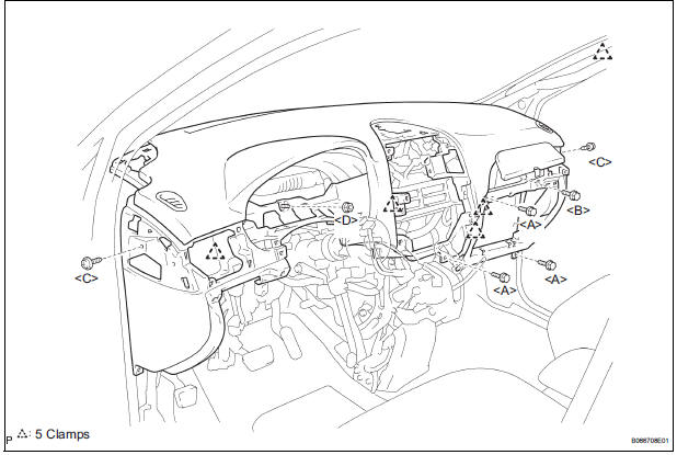
1. BOLT, SCREW AND NUT TABLE
- The bolts, the screws and the nuts, which are necessary for installation and removal of the instrument panel are shown in the illustration below with alphabets.
2. DISCONNECT BATTERY NEGATIVE TERMINAL
3. REMOVE STEERING WHEEL COVER LOWER NO.2
4. REMOVE STEERING WHEEL COVER LOWER NO.3
5. REMOVE HORN BUTTON ASSEMBLY
6. REMOVE STEERING WHEEL ASSEMBLY
7. REMOVE STEERING COLUMN COVER
8. REMOVE HEADLIGHT DIMMER SWITCH ASSEMBLY
9. REMOVE WINDSHIELD WIPER SWITCH ASSEMBLY
10. REMOVE INSTRUMENT CLUSTER FINISH PANEL SUB-ASSEMBLY
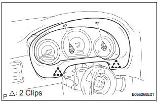
- Remove the 2 clips.
- Pull the instrument cluster finish panel subassembly rearward to remove it.
11. REMOVE COMBINATION METER ASSEMBLY
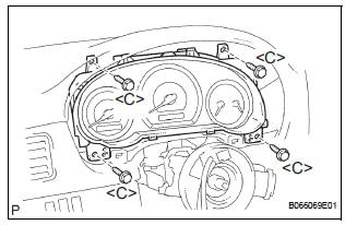
- Remove the 4 screws <C>.
- Pull out the combination meter assembly, then disconnect the connectors.
12. REMOVE FRONT DOOR SCUFF PLATE RH
13. REMOVE FRONT DOOR SCUFF PLATE LH
14. REMOVE COWL SIDE TRIM BOARD RH
15. REMOVE COWL SIDE TRIM BOARD LH
16. REMOVE INSTRUMENT PANEL FINISH PANEL SUBASSEMBLY LOWER LH
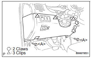
- Remove the 2 bolts <A>.
- Disconnect the hood lock control cable assembly.
- Disengage the 2 claws and 3 clips, and then remove the instrument panel finish panel sub-assembly lower LH.
- Disconnect the connectors
17. REMOVE INSTRUMENT PANEL SAFETY PAD INSERT SUB-ASSEMBLY NO.1
- Remove the 4 bolts <A> and instrument panel safety pad insert sub-assembly No. 1.
- Disconnect the connector
18. REMOVE GLOVE COMPARTMENT DOOR STOPPER SUB-ASSEMBLY
- Disengage the claw, and remove the glove compartment door stopper sub-assembly.
19. REMOVE GLOVE COMPARTMENT DOOR ASSEMBLY
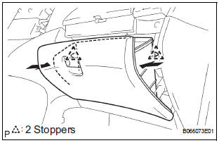
- Push the right side wall and then push the left wall to release the stoppers.
- Pull the glove compartment door sub-assembly rearward to remove it.
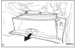
20. REMOVE INSTRUMENT PANEL BOX NO.2
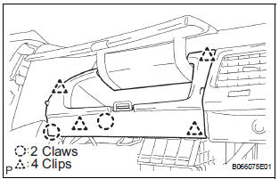
- Disengage the 2 claws and the 4 clips, and remove the instrument panel box No. 2.
21. REMOVE INSTRUMENT SIDE PANEL LH
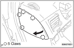
- Disengage the 5 claws by pulling up the edge of the instrument side panel LH from the rear of the vehicle.
- Remove the instrument side panel LH.
22. REMOVE INSTRUMENT SIDE PANEL RH
23. REMOVE INSTRUMENT PANEL REGISTER ASSEMBLY NO.1
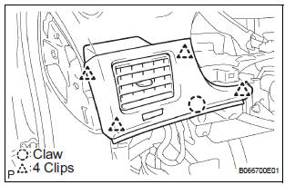
- Disengage the claw and 4 clips, and then remove the instrument panel register assembly No. 1.
24. REMOVE INSTRUMENT PANEL REGISTER ASSEMBLY NO.3
25. REMOVE FLOOR CARPET COVER CENTER LH
- Remove the clip on the floor carpet cover center LH.
- Depress the edge of the floor carpet cover center LH around the claws to disengage the two claws under beneath of the floor carpet cover center LH.
- Slightly sliding the floor carpet cover center LH to the front of the vehicle, detach the two claws from the instrument cluster finish panel sub-assembly lower center at the floor carpet cover center LH.
- Remove the floor carpet cover center LH.
26. REMOVE FLOOR CARPET COVER CENTER RH
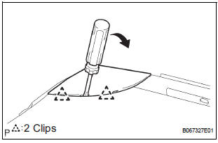
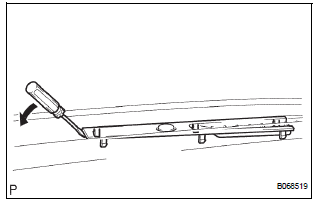
27. REMOVE INSTRUMENT CLUSTER FINISH PANEL CENTER NO.1
- Using a moulding remover, disengage the 3 clips as shown in the illustration.
- Disconnect the connector and remove the instrument cluster finish panel center No. 1.
28. REMOVE INSTRUMENT CLUSTER FINISH PANEL CENTER NO.2
29. REMOVE SHIFT LEVER KNOB SUB-ASSEMBLY
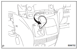
- Remove the floor shift lever knob sub-assembly.
30. REMOVE FLOOR SHIFT POSITION INDICATOR HOUSING ASSEMBLY
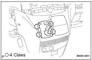
- Disengage the 4 claws, and remove the floor shift position indicator housing assembly.
31. REMOVE INSTRUMENT CLUSTER FINISH PANEL ASSEMBLY CENTER
- Remove the screw <C>.
- Disengage the 5 clips and the claw from the lowest part on the instrument cluster finish panel assembly center in order.
- Disconnect the connectors at the instrument cluster finish panel sub-assembly lower center, and then remove the instrument cluster finish panel assembly center.
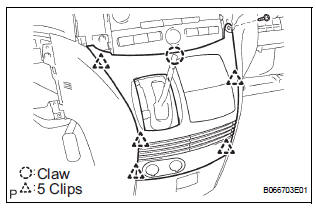
32. REMOVE INSTRUMENT CLUSTER FINISH PANEL SUB-ASSEMBLY LOWER CENTER
- Remove the 2 clips on both sides.
- Remove the 3 screws <C> and 3 bolts <A>.
- Pull the instrument cluster finish panel subassembly lower center rearward to remove it.
- Disconnect the connector.
33. REMOVE INSTRUMENT CLUSTER FINISH PANEL GARNISH
- Insert the edge of a moulding remover between the instrument cluster finish panel garnish and the radio receiver from the top center, and then lean the moulding remover toward the front of the vehicle to raise the instrument cluster finish panel garnish.
- Disengage the claw on the top of the instrument cluster finish panel garnish and the two clips from the radio receiver.
- Pull up the instrument cluster finish panel garnish to the front of the vehicle to disengage the 5 claws at the bottom of the instrument cluster finish panel garnish.
- Remove the instrument cluster finish panel garnish.
34. REMOVE STEREO COMPONENT SPEAKER ASSEMBLY
- Remove the 2 screws and stereo component speaker assembly.
- Disconnect the connector.
35. REMOVE NAVIGATION RECEIVER ASSEMBLY
36. REMOVE INTEGRATION CONTROL AND PANEL ASSEMBLY
37. REMOVE FRONT PILLAR GARNISH RH
38. REMOVE FRONT PILLAR GARNISH LH
39. REMOVE INSTRUMENT PANEL SPEAKER PANEL SUB-ASSEMBLY
- Using a screwdriver, disengage the 2 clips and remove the instrument panel speaker panel subassembly.
40. REMOVE INSTRUMENT PANEL SPEAKER PANEL SUB-ASSEMBLY NO.2
41. REMOVE FRONT NO.1 SPEAKER ASSEMBLY
- Remove the 2 screws and front No. 1 speaker assembly.
- Disconnect the connector.
42. REMOVE FRONT NO.2 SPEAKER ASSEMBLY
43. REMOVE DEFROSTER NOZZLE OPENING PLATE NO.1
- Using a screwdriver, disengage the 6 claws and remove the defroster nozzle opening plate No. 1.
- Disconnect the connector.
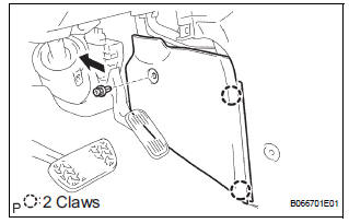
44. SEPARATE SHIFT LEVER ASSEMBLY
- Remove the 4 bolts and separate the shift lever assembly.
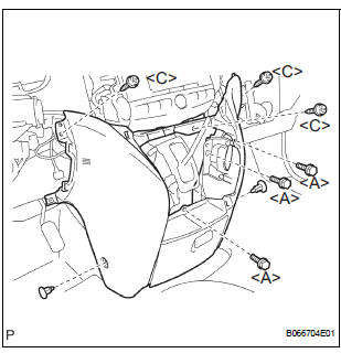
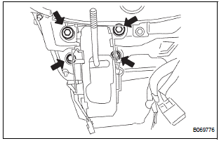
45. REMOVE INSTRUMENT PANEL SAFETY PAD SUBASSEMBLY
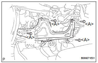
- Remove the 4 bolts <A> <B> and 2 screws <C> and a nut <E>.
- Disconnect the connectors.
- Remove the instrument panel sub-assembly w/ passenger airbag assembly.
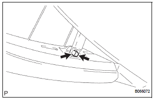
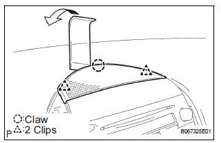
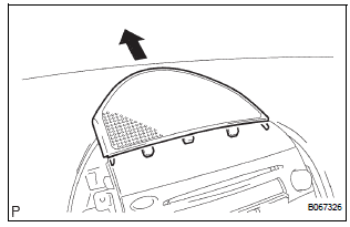
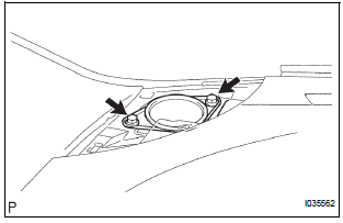
46. REMOVE NAVIGATION ANTENNA ASSEMBLY
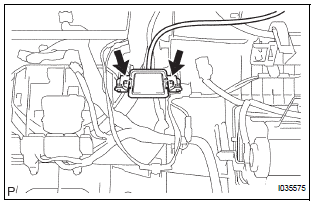
- Release the 3 clamps and remove the 2 screws and the navigation antenna assembly.
 Navigation antenna
COMPONENTS
...
 Installation
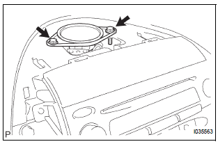
1. INSTALL NAVIGATION ANTENNA ASSEMBLY
2. INSTALL INSTRUMENT PANEL SAFETY PAD SUBASSEMBLY
Using a torque wrench, install the bolt <B>.
Torque: 20 N*m (204 kgf*cm, 14 ft.*lbf)
...
Other materials:
Short in Curtain Shield Squib LH Circuit
DTC B1165/87 Short in Curtain Shield Squib LH Circuit
DESCRIPTION
The curtain shield squib LH circuit consists of the center airbag sensor
assembly and the curtain shield
airbag assembly LH.
The circuit instructs the SRS to deploy when deployment conditions are met.
DTC B1165/87 is record ...
Air conditioning pressure sensor
ON-VEHICLE INSPECTION
1. INSPECT A/C PRESSURE SENSOR
(a) Install the manifold gauge set.
(b) Disconnect the connector from the A/C pressure
sensor.
(c) Connect the three 1.5 V dry cell batteries' positive
(+) lead to terminal 3 and the negative (-) lead to
terminal 1.
(d) Connect t ...
Installation
1. INSTALL CENTER AIRBAG SENSOR ASSEMBLY
Check that the ignition switch is off.
Check that the battery negative (-) terminal is
disconnected.
CAUTION:
After disconnecting the negative battery
terminal, wait for at least 90 seconds before
starting the operation.
Temporar ...
