Toyota Sienna Service Manual: Removal
HINT: On the RH side, use the same procedures as on the LH side.
1. REMOVE SLIDE DOOR
- Remove the rear door scuff plate (See page IR-7).
- Remove the back door scuff plate (See page ED- 214).
- Remove the quarter trim panel (See page IR-9).
- Remove the upper rail cushion from the rail upper.
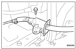
- Disconnect the 2 connectors from the body side and remove the bolt and wire.
- Open the quarter glass.
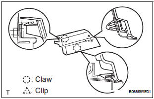
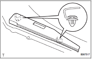
- Using a screwdriver, disengage the clip and 2 claws, remove the rail end moulding.
HINT: Tape the screwdriver tip before use.
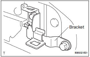
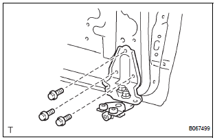
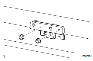
- Remove the 2 bolts and bracket center No. 2.
- Remove the 2 nuts and open stop.
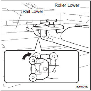
- Rotate the base of the slide door roller lower in the direction indicated by arrow in the illustration and then remove the roller from the cut area of the lower rail from the body side.
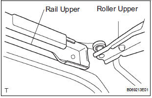
- Move the slide door rearward and then remove the slide door roller upper from the cut area in the rear part of the slide door rail upper.
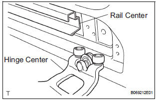
- Move the slide door further rearward and then remove the slide door hinge center from the rear part of the slide door rail center. Then, remove the slide door.
2. REMOVE SLIDE DOOR RAILS
- Remove the roof headlining (See page IR-6).
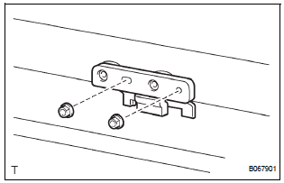
- Remove the 2 bolts, 2 nuts and the rail upper.
- Remove the 2 screws and the rear side rail.
- Remove the 3 screws and the rail center.
3. REMOVE SLIDE DOOR FULL OPEN STOP LOCK ASSEMBLY LH
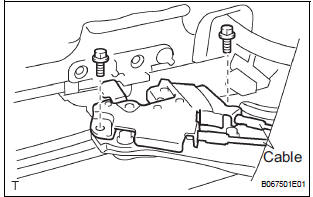
- Disconnect the 2 cables.
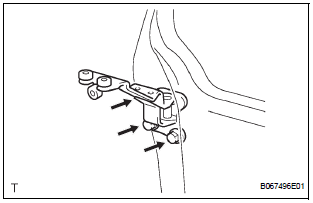
- Remove the 2 bolts and lock
4. REMOVE SLIDE DOOR ROLLER ASSEMBLY LOWER LH
- Remove the 3 bolts and roller.
5. REMOVE SLIDE DOOR HINGE ASSEMBLY CENTER LH
- Remove the 3 bolts and hinge.
- LH side: Remove the cover.
6. REMOVE SLIDE DOOR ROLLER ASSEMBLY UPPER
- Remove the 2 bolts and roller.
7. REPLACE SLIDE DOOR HALF OPEN STOPPER SUBASSEMBLY
- Using a screwdriver, remove the 2 clips and cover.
HINT: Tape the screwdriver tip before use.
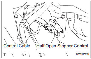
- Remove the 2 bolts and disconnect the control cable from the open striker.
- Disconnect the control cable from the half open stopper.
- Remove the 2 bolts and half open stopper.
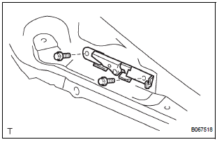
8. REPLACE SLIDE DOOR HALF OPEN STOPPER CONTROL ASSEMBLY
- Remove the 2 nuts and half open stopper control.
- Remove the control cable.
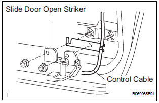
9. REPLACE SLIDE DOOR OPEN STRIKER LH
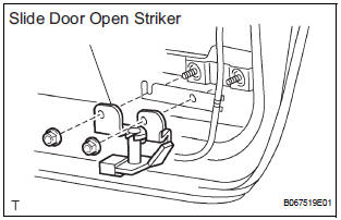
- Remove the 2 nuts and open striker.
10. REPLACE SLIDE DOOR OPEN STRIKER RH
HINT: Use the same procedures for the LH side.
11. REPLACE SLIDE DOOR OPEN STOP LH
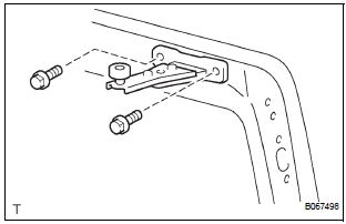
- Remove the 2 nuts and open stop.
12. REPLACE SLIDE DOOR OPEN STOP RH
HINT: Use the same procedures for the LH side.
 Slide door
COMPONENTS
...
 Disassembly
HINT:
On the RH side, use the same procedures as on the LH side.
1. REMOVE REAR DOOR WINDOW FRAME MOULDING
REAR LH (See page ET-30)
2. REMOVE REAR DOOR WINDOW FRAME MOULDING
SUB-ASSEMBLY LH (See ...
Other materials:
Evaporator temperature sensor circuit
DESCRIPTION
The evaporator temperature sensor (A/C thermistor) is installed on the
evaporator in the air conditioning
unit. It detects the temperature of the cooled air that has passed through the
evaporator and its signal is
used to control the air conditioning. It sends a signal to the A/C ...
Ignition Coil Primary / Secondary Circuit
DTC P0351 Ignition Coil "A" Primary / Secondary Circuit
DTC P0352 Ignition Coil "B" Primary / Secondary Circuit
DTC P0353 Ignition Coil "C" Primary / Secondary Circuit
DTC P0354 Ignition Coil "D" Primary / Secondary Circuit
DTC P0355 Ignition Coil "E& ...
Installation
1. INSTALL TIRE PRESSURE WARNING ECU
(a) Connect the connector to the tire pressure warning
ECU.
(b) Install the tire pressure warning ECU with the screw.
2. INSTALL INSTRUMENT PANEL SAFETY PAD SUBASSEMBLY
HINT:
Refer to the instructions for INSTALLATION of the
instrument panel safety ...
