Toyota Sienna Service Manual: Removal
HINT: On the LH side, use the same procedures as on the RH side.
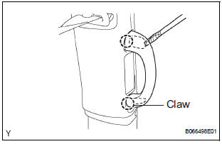
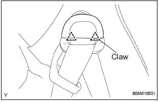
1. REMOVE FRONT DOOR SCUFF PLATE RH
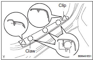
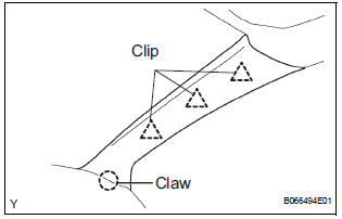
- Using a screwdriver, disengage the 3 clips and 2 claws, and remove the scuff plate.
HINT: Tape the screwdriver tip before use.
2. REMOVE FRONT DOOR SCUFF PLATE LH
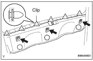
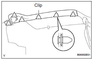
3. REMOVE REAR DOOR SCUFF PLATE RH
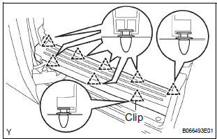
- Using a screwdriver, disengage the 8 clips and remove the scuff plate.
HINT: Tape the screwdriver tip before use.
4. REMOVE REAR DOOR SCUFF PLATE LH
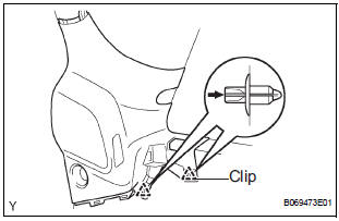
5. REMOVE COWL SIDE TRIM BOARD RH
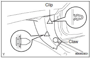
- Using a screwdriver, disengage the 2 clips and claw, and remove the trim board.
HINT: Tape the screwdriver tip before use.
6. REMOVE COWL SIDE TRIM BOARD LH
7. REMOVE FRONT DOOR OPENING TRIM WEATHERSTRIP RH
8. REMOVE FRONT DOOR OPENING TRIM WEATHERSTRIP LH
9. REMOVE REAR DOOR WEATHERSTRIP RH
HINT: When reinstalling the weatherstrip, completely remove the sealer adhering to the opening flange on the body side beforehand.
10. REMOVE REAR DOOR WEATHERSTRIP LH
HINT: When reinstalling the weatherstrip, completely remove the sealer adhering to the opening flange on the body side beforehand.
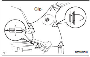
11. REMOVE CENTER PILLAR GARNISH LOWER RH
- Remove the floor anchor cover.
- Remove the bolt and disconnect the front seat outer belt on the floor anchor side.
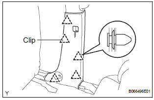
- Using a screwdriver, disengage the 5 clips and
remove the pillar garnish.
HINT: Tape the screwdriver tip before use.
- w/ power slide door: Disconnect the power slide door control switch RH connector.
12. REMOVE CENTER PILLAR GARNISH LOWER LH
13. REMOVE CENTER PILLAR GARNISH UPPER RH
- Using a screwdriver, disengage the assist grip
plugs.
HINT: Tape the screwdriver tip before use.
- Remove the 2 torx screws and assist grip No. 2 RH.
- Remove the 3 bolts.
- Using a screwdriver, disengage the clip and remove the pillar garnish.
HINT: Tape the screwdriver tip before use.
14. REMOVE CENTER PILLAR GARNISH UPPER LH
HINT: Use the same procedures described above for the RH side.
15. REMOVE BACK DOOR WEATHERSTRIP
16. REMOVE BACK DOOR SCUFF PLATE
- Remove the 3 bolts.
- Using a screwdriver, disengage the 6 clips and remove the scuff plate.
HINT: Tape the screwdriver tip before use
17. REMOVE QUARTER TRIM PANEL ASSEMBLY FRONT RH
- Remove the floor anchor cover.
- Remove the bolt and disconnect the rear No. 2 seat belt on the floor anchor side.
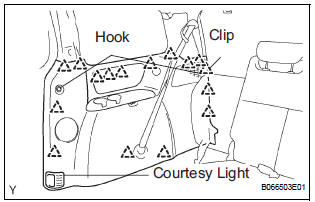
- Remove the 2 package holder net hooks.
- Using a screwdriver, disengage the claw and remove the courtesy light.
- Disconnect the courtesy light connectors.
- Using a screwdriver, disengage the 16 clips and remove the quarter trim panel assembly.
HINT: Tape the screwdriver tip before use.
18. REMOVE QUARTER TRIM PANEL ASSEMBLY FRONT LH
19. REMOVE ROOF HEADLINING GARNISH REAR
- Using a screwdriver, disengage the 6 clips and remove the headlining garnish.
HINT: Tape the screwdriver tip before use.
20. REMOVE RR WINDOW SIDE GARNISH ASSEMBLY NO.2 RH
- Using a screwdriver, disengage the 2 claws and
remove the cover of the rear No. 2 seat belt on the
shoulder anchor side.
HINT: Tape the screwdriver tip before use.
- Remove the bolt and disconnect the rear No. 2 seat belt assembly on the shoulder anchor side.
- Using a screwdriver, disengage the 5 clips and remove the side garnish.
HINT: Tape the screwdriver tip before use.
21. REMOVE RR WINDOW SIDE GARNISH ASSEMBLY NO.2 LH
- w/ power back door: Using a screwdriver, disengage the 2 clips and remove the window side garnish assembly.
HINT: Tape the screwdriver tip before use.
22. REMOVE RR WINDOW SIDE GARNISH ASSEMBLY RH
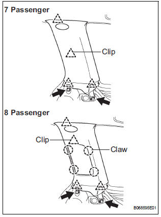
- Remove the bolt and screw.
- 7-passenger:
Using a screwdriver, disengage the 4 clips and
remove the window side garnish assembly.
HINT: Tape the screwdriver tip before use.
- 8-passenger: Using a screwdriver, disengage the 4 clips and 4 claws, and remove the window side garnish assembly.
HINT: Tape the screwdriver tip before use.
23. REMOVE RR WINDOW SIDE GARNISH ASSEMBLY LH
24. REMOVE FRONT PILLAR GARNISH RH
- w/ curtain shield airbag: Using a screwdriver, disengage the cover of the pillar garnish and bolt.
HINT: Tape the screwdriver tip before use.
- Using a screwdriver, disengage the 3 clips and claw and remove the pillar garnish.
HINT: Tape the screwdriver tip before use.
- Pull the garnish upward and remove it from the instrument panel.
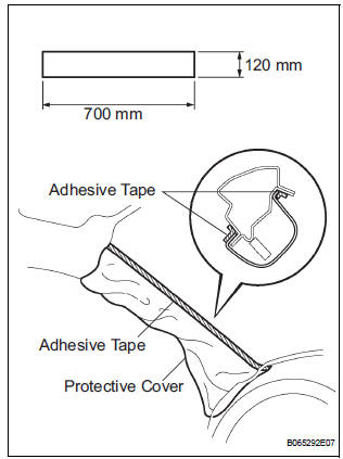
- w/ curtain shield airbag: Protect the curtain shield airbag LH.
- Thoroughly cover the airbag with cloth or nylon of 700 mm (27.56 in.) x 120 mm (4.72 in.) and fix the ends of the cover with adhesive tape, as shown in the illustration.
NOTICE: Cover the curtain shield airbag with the protection cover as soon as the pillar garnish is removed.
25. REMOVE FRONT PILLAR GARNISH LH
26. REMOVE RH VISOR ASSEMBLY
- Using a screwdriver, disengage the 2 claws and
remove the visor cover.
HINT: Tape the screwdriver tip before use.
- Remove the 3 screws and visor.
27. REMOVE LH VISOR ASSEMBLY
28. REMOVE VISOR HOLDER
- Remove the screw and visor holder.
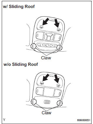
29. REMOVE ROOF CONSOLE BOX ASSEMBLY
- Remove the 2 screws and console box assembly.
- Using a moulding remover, disengage the 2 claws.
- Disconnect the map light switch connector and sliding roof switch connector and remove the console box.
30. REMOVE ASSIST GRIP SUB-ASSEMBLY
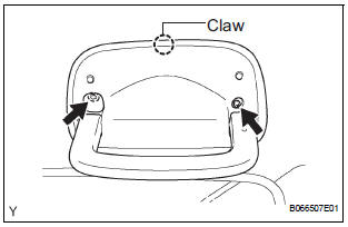
- Using a screwdriver, disengage the claw and
remove the assist grip cover.
HINT: Tape the screwdriver tip before use.
- Remove the torx, screw and assist grip subassembly.
31. REMOVE ROOF CONSOLE BOX
- Remove the 2 torx screws, 2 screws and roof console box.
32. REMOVE AIR CONDITIONING NO.2 CONTROL ASSEMBLY
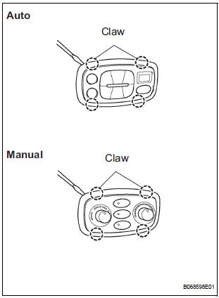
- Using a screwdriver, disengage the 4 claws and
remove the heater control base.
HINT: Tape the screwdriver tip before use.
- Remove the No. 2 control assembly.
- Disconnect the No. 2 control connector
33. REMOVE AIR OUTLET REGISTER ASSEMBLY NO.1
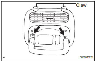
- Using a screwdriver, disengage the 2 claws, and
remove the cover.
HINT: Tape the screwdriver tip before use.
- Remove the bolt, screw and air outlet register.
34. REMOVE AIR OUTLET REGISTER ASSEMBLY NO.2
35. REMOVE AIR DUCT REGISTER ASSEMBLY NO.3
36. REMOVE AIR OUTLET REGISTER ASSEMBLY NO.4
37. REMOVE SUN ROOF OPENING TRIM MOULDING (w/ Sliding Roof)
38. REMOVE ROOF HEADLINING ASSEMBLY
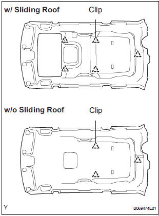
- w/ sliding roof: Using a clip remover, disengage the 5 clips and remove the roof headlining assembly.
- w/o sliding roof: Using a clip remover, disengage the 3 clips and remove the roof headlining assembly.
NOTICE: In order to prevent the roof headlining from becoming bent, work must be performed by 2 or more persons when removing/installing it
 Roof headlining
COMPONENTS
...
 Installation
1. INSTALL ROOF HEADLINING ASSEMBLY
w/ sliding roof:
Install the roof headlining with the 5 clips.
w/o sliding roof:
Install the roof headlining with the 3 clips.
NOTICE:
In order to ...
Other materials:
Pressure Control Solenoid "C" Performance (Shift
Solenoid Valve SL3)
SYSTEM DESCRIPTION
The ECM uses signals from the vehicle speed sensor to detect the actual gear
position (1st, 2nd, 3rd, 4th
or 5th gear).
Then the ECM compares the actual gear with the shift schedule in the ECM memory
to detect mechanical
troubles of the shift solenoid valves and valve bo ...
Freeze frame data
1. FREEZE FRAME DATA
(a) The vehicle (sensor) status, stored during ABS and/
or VSC operation or at the time of an error code
detection, can be displayed by the intelligent tester.
(b) Only one record of freeze frame data is stored and
the freeze frame data generated during ABS and/or
VSC op ...
Installation
1. INSTALL RADIO NO. 2 BRACKET
Install radio No. 2 bracket with the 4 screws.
2. INSTALL RADIO NO. 1 BRACKET
Install radio No. 1 bracket with the 4 screws.
3. INSTALL RADIO RECEIVER
Connect the connector.
Install the radio receiver with the 4 scr ...
