Toyota Sienna Service Manual: Removal
1. DISCONNECT CABLE FROM NEGATIVE BATTERY TERMINALV
| Caution: wait at least 90 seconds after disconnecting the cable from the negative (-) battery terminal to prevent airbag and seat belt pretensioner activation. |
2. Remove air fuel ratio sensor (for bank 2 sensor 1)
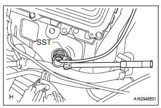
(a) Disconnect the sensor connector.
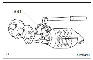
(b) Using SST, remove the sensor from the exhaust manifold.V
Sst 09224-00010
3. REMOVE CENTER EXHAUST PIPE ASSEMBLY
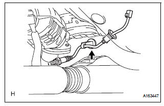
(a) Disconnect the heated oxygen sensor (for Bank 1 Sensor 2) connector under the center console.
(b) Remove the clip as shown in the illustration.

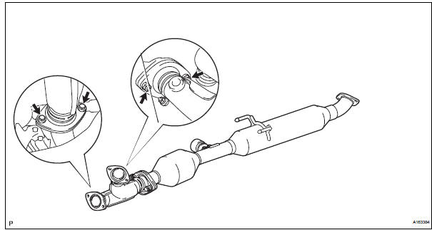
(c) Remove the 2 bolts and 2 compression springs.
(d) Remove the 2 bolts, 2 nuts and center exhaust pipe assembly.
4. REMOVE EXHAUST MANIFOLD RH

(a) Remove the nut, bolt and exhaust manifold stay.
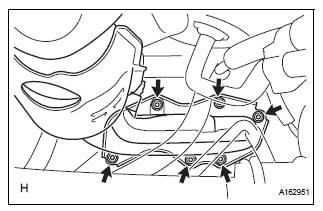
(b) Remove the 6 nuts and exhaust manifold RH.
(c) Remove the gasket and exhaust manifold to head gasket.
5. REMOVE AIR FUEL RATIO SENSOR (for Bank 1 Sensor 1)
(a) Using SST, remove the sensor.
SST 09224-00010
 On-vehicle inspection
HINT:
The type of ignition switch on this model differs according to
the specifications of the vehicle. For the expressions used in
this section, refer to the "EXPRESSIONS OF IGNITION
SWITCH& ...
 Inspection
1. Inspect air fuel ratio sensor
(A) measure the resistance of the sensor.
Standard resistance
If the resistance is not as specified, replace the
sensor.
...
Other materials:
Air Mix Damper Position Sensor Circuit (Passenger Side)
DESCRIPTION
This sensor detects the position of the air mix control servo motor (air mix
damper) and sends the
appropriate signals to the A/C amplifier. The position sensor is built in the
air mix control servo motor. The
position sensor's resistance changes as the air mix control servo m ...
Terminals of ECU
1. TELEVISION CAMERA ASSEMBLY
Disconnect the T10 camera connector
Measure the voltage and resistance of each
terminal of the wire harness side connector.
If the result is not as specified, there may be a
malfunction on the wire harness side.
Reconnect the T10 ...
Catalyst monitor (active air-fuel ratio control
type)
(a) Preconditions
The monitor will not run unless:
The MIL is OFF.
(b) Drive Pattern
(1) Connect an intelligent tester.
(2) Turn the ignition switch to the ON position.
(3) Turn the tester or scan tool ON.
(4) Clear the DTCs.
(5) Start the engine and warm it up.
(6) Drive ...
