Toyota Sienna Service Manual: Removal
1. Remove no. 2 Air cleaner inlet (see page em- 28) 2. Remove air cleaner cap sub-assembly
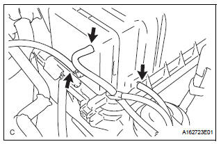
(a) Disconnect the 3 vacuum hoses.
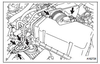
(b) Loosen the bolt, disconnect the 2 connectors, and remove the 2 vacuum hoses.
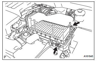
(c) Remove the 2 bolts, air cleaner cap sub-assembly, and air cleaner filter element.
3. REMOVE NO. 3 INTAKE AIR CONTROL VALVE ASSEMBLY
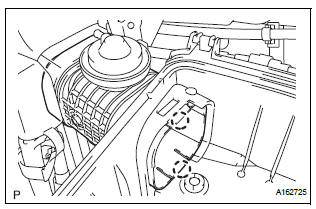
(a) Disengage the 2 claws and remove the No. 3 intake air control valve assembly.
 On-vehicle inspection
1. Inspect intake air surge tank assembly
(A) inspection procedure when applying voltage
between the terminals:
(1) Disconnect the connector from the intake air
control valve.
(2) Apply bat ...
 Inspection
1. Inspect no. 3 Intake air control valve
assembly
(A) inspect actuator operation.
(1) With 26.7 Kpa (200 mm hg, 7.9 In. Hg) of
vacuum applied to the actuator, check that the
actuator rod m ...
Other materials:
On-vehicle inspection
1. INSPECT SIDE AIRBAG SENSOR (VEHICLE NOT
INVOLVED IN COLLISION)
Perform a diagnostic system check.
2. INSPECT SIDE AIRBAG SENSOR (VEHICLE
INVOLVED IN COLLISION AND AIRBAG HAS NOT
DEPLOYED)
Perform a diagnostic system check.
When the center pillar of the vehicle or its a ...
Installation
1. INSTALL TIRE PRESSURE WARNING RESET SWITCH
(a) Engage the 2 claws to install the tire pressure
warning reset switch to the lower instrument panel
finish panel sub-assembly LH.
2. INSTALL LOWER INSTRUMENT PANEL FINISH
PANEL SUB-ASSEMBLY LH
3. INSTALL COWL SIDE TRIM SUB-ASSEMBLY LH
4. IN ...
Touch screen gestures
Operations are performed by touching the screen directly with your
finger.
Operation method
Outline
Main use
Touch
Quickly touch and
release once.
Changing and selecting
various settings.
Drag*
Touch the screen
with your ...
