Toyota Sienna Service Manual: Removal
1. REMOVE ENGINE ASSEMBLY WITH TRANSAXLE
HINT: See page EM-26
2. SECURE ENGINE (See page EM-37) 3. REMOVE GENERATOR ASSEMBLY (See page CH-17) 4. REMOVE COMPRESSOR AND MAGNETIC CLUTCH (See page AC-227) 5. REMOVE NO. 1 ENGINE FRONT MOUNTING BRACKET LH (See page EM-42) 6. REMOVE NO. 2 IDLER PULLEY SUB-ASSEMBLY
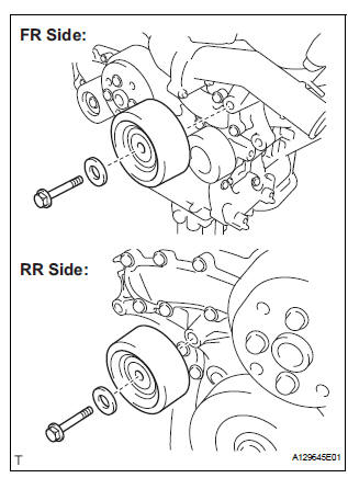
(a) Remove the 2 bolts, 2 idler pulley cover plates and 2 idler pulley sub-assemblies.
7. REMOVE V-RIBBED BELT TENSIONER ASSEMBLY
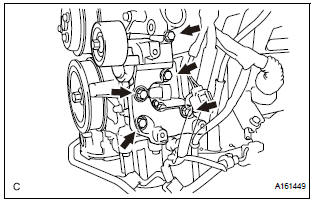
(a) Remove the 5 bolts and V-ribbed belt tensioner assembly.
8. REMOVE WATER PUMP PULLEY
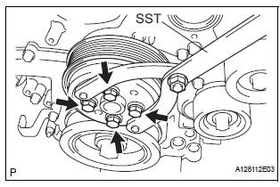
(a) Using SST, hold the water pump pulley.
SST 09960-10010 (09962-01000, 09963-00700) (b) Remove the 4 bolts and water pump pulley.
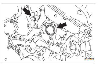
9. REMOVE WATER INLET HOUSING
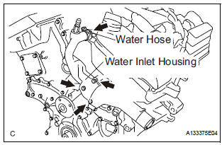
(a) Disconnect the water hose.
(b) Remove the 2 bolts, nut and water inlet housing.
(c) Remove the water inlet housing gasket and water outlet pipe O-ring.
10. REMOVE WATER PUMP ASSEMBLY
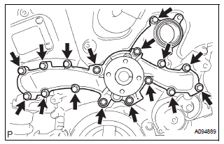
(a) Remove the 16 bolts, water pump assembly and water pump gasket.
 Water pump
COMPONENTS
...
 Inspection
1. Inspect water pump assembly
(a) Visually check the drain hole and air hole for coolant
leakage.
(b) Turn the pulley, and check that the water pump
bearing moves smoothly and noiselessly.
...
Other materials:
Rear Air Mix Damper Position Sensor Circuit
DESCRIPTION
This sensor detects the position of the rear air mix control servo motor
(water valve servo motor) and
sends the appropriate signals to the A/C amplifier. The position sensor is built
in the rear air mix control
servo motor (water valve servo motor).
The position sensor's r ...
Camshaft Position Sensor
DTC P0365 Camshaft Position Sensor "B" Circuit (Bank 1)
DTC P0367 Camshaft Position Sensor "B" Circuit Low
Input (Bank 1)
DTC P0368 Camshaft Position Sensor "B" Circuit High
Input (Bank 1)
DTC P0390 Camshaft Position Sensor "B" Circuit (Bank 2)
DTC P0392 ...
Rear Airbag Sensor RH Circuit Malfunction
DTC B1154/38 Rear Airbag Sensor RH Circuit Malfunction
DESCRIPTION
The rear airbag sensor RH circuit consists of the center airbag sensor
assembly and rear airbag sensor
RH.
If the center airbag sensor assembly receives signals from the rear airbag
sensor RH, it judges whether or
not the ...
