Toyota Sienna Service Manual: Removal
1. REMOVE V-BANK COVER SUB-ASSEMBLY (See page EM-28) 2. REMOVE NO. 1 ENGINE UNDER COVER (See page EM-26) 3. DRAIN ENGINE COOLANT (See page CO-6) 4. REMOVE FRONT WHEEL RH 5. REMOVE FRONT FENDER APRON SEAL RH 6. REMOVE V-RIBBED BELT (See page EM-6) 7. DISCONNECT NO. 2 RADIATOR HOSE
(a) Disconnect the No. 2 radiator hose from the engine.
8. REMOVE NO. 2 IDLER PULLEY SUB-ASSEMBLY
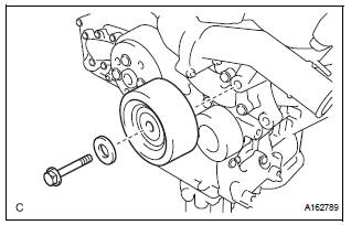
(a) Remove the bolt, idler pulley cover plate and idler pulley sub-assembly.
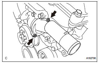
9. REMOVE WATER INLET
(a) Remove the 2 nuts and water inlet.
10. REMOVE THERMOSTAT
(a) Remove the gasket from the thermostat.
 Thermostat
Components
...
 Inspection
1. INSPECT THERMOSTAT
(a) Inspect the thermostat.
HINT:
The valve opening temperature is inscribed on the
thermostat.
(b) Immerse the thermostat in water and gradually heat
the water.
...
Other materials:
Power easy access system
The seat is automatically adjusted to allow the driver to enter and exit
the vehicle easily.
When all of the following have
been performed, the driver’s seat
is automatically adjusted to a
position that allows driver to enter
and exit the vehicle easily.
The shift lever has been sh ...
Initialization
1. ZERO POINT CALIBRATION
NOTICE:
Make sure that the front passenger seat is not
occupied before performing the operation.
HINT:
Perform the zero point calibration and sensitivity check if
any of the following conditions occur.
The occupant classification ECU is replaced.
A ...
Actuator Supply Voltage Circuit / Open
DTC P0657 Actuator Supply Voltage Circuit / Open
DESCRIPTION
The ECM monitors the output voltage to the throttle actuator. This self-check
ensures that the ECM is
functioning properly. The output voltage is usually 0 V when the ignition switch
is turned off. If the output
voltage is higher t ...
