Toyota Sienna Service Manual: Removal
1. DISCONNECT CABLE FROM NEGATIVE BATTERY TERMINAL 2. DRAIN ENGINE COOLANT 3. REMOVE FRONT WIPER ARM HEAD CAP (See page WW-4) 4. REMOVE FRONT WIPER ARM RH (See page WW-4) 5. REMOVE FRONT WIPER ARM LH (See page WW-4) 6. REMOVE COWL TOP VENTILATOR LOUVER SUBASSEMBLY (See page WW-4) 7. REMOVE WINDSHIELD WIPER MOTOR AND LINK ASSEMBLY (See page WW-4) 8. REMOVE NO. 1 COWL TOP TO COWL BRACE INNER (See page FU-13) 9. REMOVE COWL TOP PANEL SUB-ASSEMBLY OUTER FRONT (See page FU-13) 10. REMOVE NO. 1 ENGINE UNDER COVER 11. REMOVE V-BANK COVER SUB-ASSEMBLY (See page EM-28) 12. REMOVE AIR CLEANER CAP SUB-ASSEMBLY (See page FU-13) 13. REMOVE INTAKE AIR SURGE TANK ASSEMBLY (See page FU-14) 14. REMOVE NO. 1 SURGE TANK STAY
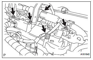
(a) Remove the 2 bolts and nut and disconnect the 2 harness clamps.
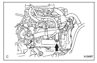
(b) Remove the bolt and No. 1 surge tank stay.
15. REMOVE IGNITION COIL ASSEMBLY
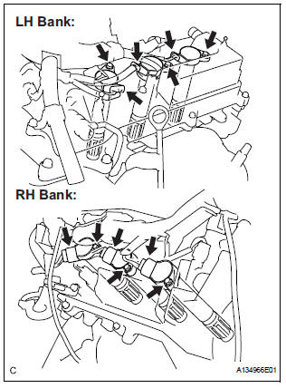
(a) Disconnect the 6 ignition coil connectors.
(b) Remove the 6 bolts and 6 ignition coils.
16. REMOVE SPARK PLUG
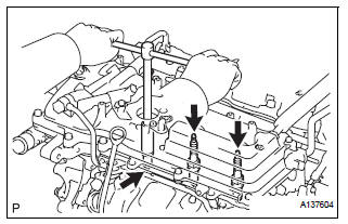
(a) Remove the 6 spark plugs.
 On-vehicle inspection
NOTICE:
In this section, the terms "cold" and "hot" refer to the
temperature of the coils. "Cold" means approximately -
10°C (14°F) to 50°C (122°F). & ...
 Installation
1. INSTALL SPARK PLUG
(a) Install the 6 spark plugs.
Torque: 18 N*m (183 kgf*cm, 13 ft.*lbf)
2. INSTALL IGNITION COIL ASSEMBLY
(a) Install the 6 ignition coils with the 6 bolts.
Torqu ...
Other materials:
Front No. 1 speaker
COMPONENTS
ON-VEHICLE INSPECTION
1. INSPECT FRONT NO.1 SPEAKER
HINT:
Remove interior parts so that the front No.1 speaker can
be seen.
Check the speaker installation.
OK:
The speaker is securely installed.
If the result is not as specified, reinstall the front
No.1 spe ...
Installation
1. INSTALL REAR AXLE HUB & BEARING ASSEMBLY LH
(a) Install the hub & Bearing assembly LH with the 4
bolts.
Torque: 56 N*m (571 kgf*cm, 41 ft.*lbf)
2. INSPECT BEARING BACKLASH (See page AH-16)
3. INSPECT AXLE HUB DEVIATION (See page AH-16)
4. CONNECT SKID CONTROL SENSOR WIRE
(a) Co ...
Short to GND in Rear Curtain Shield Squib LH
Circuit
DTC B1637/85 Short to GND in Rear Curtain Shield Squib LH
Circuit
DESCRIPTION
The rear curtain shield squib LH circuit consists of the center airbag sensor
assembly and the curtain
shield airbag assembly LH.
The circuit instructs the SRS to deploy when deployment conditions are met.
DTC ...
