Toyota Sienna Service Manual: Removal
1. Remove v-bank cover sub-assembly (see page em-28) 2. Remove front wheel rh 3. Remove no. 1 Engine under cover (see page em-26) 4. Remove front fender apron seal rh (see page em-26) 5. Drain engine coolant (see page co-6) 6. Remove no. 2 Air cleaner inlet (see page em- 28) 7. Remove battery (see page em-26) 8. Remove front bumper assembly (see page et-3) 9. Remove front bumper energy absorber 10. Remove no. 1 Air cleaner inlet (see page em- 28) 11. Disconnect radiator reserve tank hose or pipe (see page co-28) 12. Disconnect no. 1 Radiator hose (see page co- 28) 13. Disconnect no. 2 Radiator hose (see page co- 29) 14. Remove hood lock release lever protector (see page co-29) 15. Remove hood lock assembly (see page co-29) 16. Remove hood lock support sub-assembly (see page co-29) 17. Disconnect cooling fan ecu connector (see page co-30) 18. Remove radiator upper support subassembly (see page co-30) 19. Disconnect no. 2 Oil cooler outlet tube sub-assembly (see page co-31) 20. Remove headlight assembly rh (see page li- 69)
21. Remove radiator side deflector rh (see page co-31) 22. Remove headlight bracket rh (see page co- 32) 23. Remove pressure feed tube assembly (see page co-32)
24. REMOVE RADIATOR SUPPORT CUSHION (See page CO-32) 25. REMOVE NO. 1 RADIATOR SUPPORT (See page CO- 32) 26. REMOVE RADIATOR ASSEMBLY WITH FAN SHROUD AND FAN MOTOR (See page CO-33) 27. REMOVE V-RIBBED BELT (See page EM-6) 28. REMOVE GENERATOR ASSEMBLY
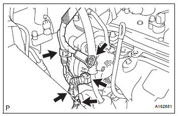
(a) Remove the terminal cap.
(b) Remove the nut and disconnect the wire harness from terminal B.
(c) Disconnect the generator connector from the generator assembly.
(d) Disconnect the connector from the compressor and magnetic clutch.
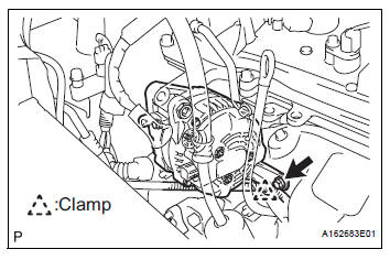
(e) Disconnect the 2 wire harness clamps.
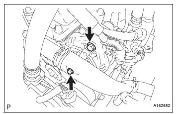
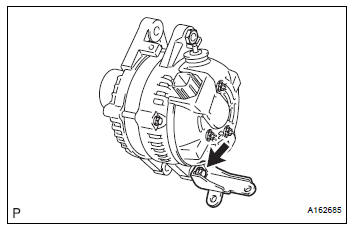
(f) Remove the 2 bolts.
(g) Remove the bolt from the cylinder block.
(h) Disconnect the wire harness clamp and remove the generator assembly.
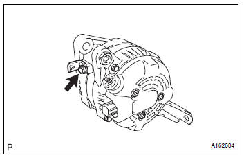
(i) Remove the bolt and wire harness clamp stay.
(j) Remove the bolt and bracket.
 Components
...
 Disassembly
1. REMOVE GENERATOR CLUTCH PULLEY
(A) using a screwdriver, remove the generator pulley
cap.
(b) Set SST (A) and (B).
SST 09820-63020
(c) Clamp SST (A) in a vise.
NOTICE:
...
Other materials:
Accelerator pedal rod
COMPONENTS
ON-VEHICLE INSPECTION
1. CHECK ACCELERATOR PEDAL ROD
(a) Check the voltage.
(1) Connect the intelligent tester to the DLC3.
(2) Turn the ignition switch to the ON position.
(3) Turn the intelligent tester on.
(4) Select the menu items: DIAGNOSIS /
ENHANCED OBD II / D ...
The Rear Cross Traffic Alert function
The Rear Cross Traffic Alert functions when your vehicle is in reverse.
It can detect other vehicles approaching from the right or left rear of
the vehicle. It uses radar sensors to alert the driver of the other vehicle’s
existence through flashing the outside rear view mirror indicators
and ...
Glove boxes
Upper glove box
Push the button.
Open the lid.
Lower glove box
The lower glove box can be opened by pulling the lever and can be
locked and unlocked by using the master key (vehicles without a
smart key) or the mechanical key (vehicles with a smart key system).
Unlo ...
