Toyota Sienna Service Manual: Removal
1. Remove engine under cover no.1 2. Disconnect cable from negative battery terminal 3. Drain automatic transaxle fluid (see page ax-131) 4. Remove automatic transaxle oil pan subassembly
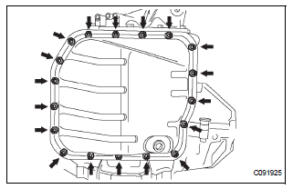
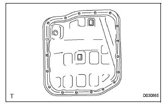
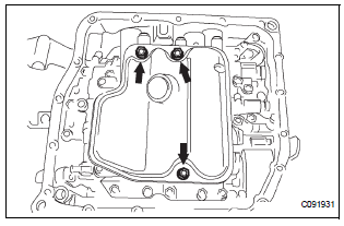
(a) Remove the 18 bolts, oil pan and gasket.
| NOTICE: Some fluid will remain in the oil pan. Carefully remove the oil pan so that the fluid remaining in the pan does not spill out. |
(b) Remove the 2 magnets from the oil pan.
(c) Examine particles in the pan.
(1) Collect any steel chips using the removed magnets. Look carefully at the chips and particles in the pan and on the magnets to see the type of wear which might be found in the transaxle.
Result: Steel (magnetic): Wear of the bearing, gear or plate Brass (non-magnetic): Wear of the bearing
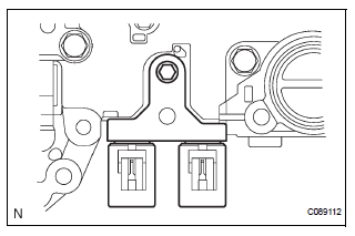
5. DISCONNECT TRANSMISSION WIRE
(a) Disconnect the 7 shift solenoid valve connectors.
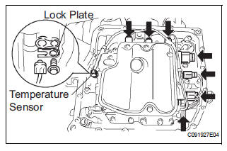
(b) Remove the bolt and lock plate, and disconnect the ATF temperature sensor.
6. REMOVE VALVE BODY OIL STRAINER ASSEMBLY
(a) Remove the 3 bolts and oil strainer.
| NOTICE: Be careful when removing the oil strainer as fluid will come out. |
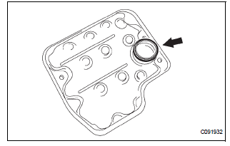
(b) Remove the O-ring from the valve body oil strainer assembly.
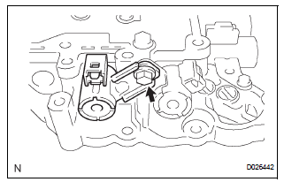
7. REMOVE TRANSMISSION VALVE BODY ASSEMBLY
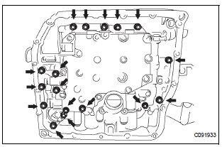
(a) Support the valve body assembly and remove the 17 bolts and the transmission valve body assembly.
(b) Remove the check ball body and the spring.
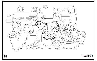
(c) Remove the bolt and lock plate from the valve body assembly.
(d) Remove the shift solenoid valve SL3 and SLT from the valve body assembly.
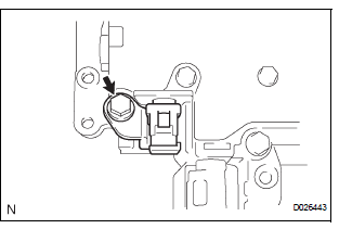
(e) Remove the bolt and shift solenoid valve S4 from the valve body assembly
(f) Remove the shift solenoid valve SR from the valve body assembly.
(g) Remove the bolt and shift solenoid valve DSL from the valve body assembly.
(h) Remove the bolt and shift solenoid valve SL2 from the valve body assembly.
(i) Remove the bolt and shift solenoid valve SL1 from the valve body assembly.
 Valve body assembly
Components
...
 Installation
1. Install transmission valve body assembly
(a) Install the shift solenoid valve SL1 to the valve body
assembly with the bolt.
Torque: 6.6 N*m (67 kgf*cm, 58 in.*lbf)
(b) Install the shi ...
Other materials:
Rear power window switch
INSPECTION
1. INSPECT POWER WINDOW REGULATOR SWITCH ASSEMBLY REAR
Check the resistance between the switch terminals
when the switch is operated.
Standard
If the result is not as specified, replace the switch
assembly. ...
Installation
HINT:
Use the same procedures for the RH side and LH side.
The procedures listed below are for the LH side.
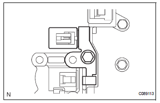
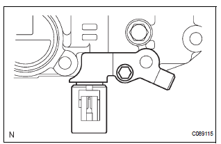
1. INSTALL REAR AIRBAG SENSOR LH
Check that the ignition switch is off.
Check that the battery negative (-) terminal is
disconnected.
CAUTION:
...
Removal
HINT:
On the RH side, use the same procedures as on the LH side.
1. REMOVE FRONT DOOR SERVICE HOLE COVER LH
Remove the front lower frame bracket garnish LH.
Remove the front door inside handle bezel plug LH.
Remove the front armrest base panel upper LH.
Remove the ...
