Toyota Sienna Service Manual: Removal
1. DISCONNECT BATTERY NEGATIVE TERMINAL 2. REMOVE FRONT DOOR SCUFF PLATE LH HINT: (See page IP-6) 3. REMOVE FRONT DOOR SCUFF PLATE RH HINT: (See page IP-6) 4. REMOVE COWL SIDE TRIM BOARD LH HINT: (See page IP-6) 5. REMOVE COWL SIDE TRIM BOARD RH HINT: (See page IP-6) 6. REMOVE INSTRUMENT PANEL FINISH PANEL SUBASSEMBLY LOWER LH HINT: (See page IP-6) 7. REMOVE GLOVE COMPARTMENT DOOR STOPPER SUB-ASSEMBLY HINT: (See page IP-7) 8. REMOVE GLOVE COMPARTMENT DOOR ASSEMBLY HINT: (See page IP-7) 9. REMOVE FLOOR CARPET COVER CENTER LH HINT: (See page IP-8) 10. REMOVE FLOOR CARPET COVER CENTER RH HINT: (See page IP-8) 11. REMOVE INSTRUMENT CLUSTER FINISH PANEL CENTER NO.1 HINT: (See page IP-8) 12. REMOVE INSTRUMENT CLUSTER FINISH PANEL CENTER NO.2 HINT: (See page IP-8)
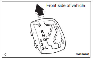
13. REMOVE SHIFT LEVER KNOB SUB-ASSEMBLY
(a) Remove the floor shift lever knob sub-assembly.
14. REMOVE POSITION INDICATOR HOUSING ASSEMBLY
(a) Using a screwdriver, remove the position indicator housing assembly from the instrument cluster finish panel assembly center.
15. REMOVE INSTRUMENT CLUSTER FINISH PANEL ASSEMBLY CENTER
HINT: (See page IP-9)
16. REMOVE SHIFT LEVER CAP
(a) Using a small screwdriver, remove the shift lever cap from the position indicator housing assembly.
17. REMOVE INSTRUMENT CLUSTER FINISH PANEL SUB-ASSEMBLY LOWER CENTER
HINT: (See page IP-9)
18. DISCONNECT TRANSMISSION CONTROL CABLE ASSEMBLY
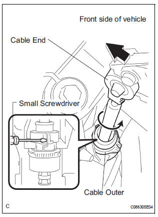
(a) Using a screwdriver, disconnect the cable end from the shift lever assembly.
(b) Using a small screwdriver, disconnect the outer of transmission control cable assembly from the shift lever assembly.
19. REMOVE SHIFT LEVER ASSEMBLY
(a) Disconnect the 2 connectors.
(b) Remove the 4 bolts and disconnect the shift lever assembly from the vehicle.
 Shift lever
Components
...
 Disassembly
1. REMOVE INDICATOR LIGHT WIRE SUB-ASSEMBLY
(a) Remove the indicator light wire sub assembly from
the position indicator light guide.
2. REMOVE POSITION INDICATOR LIGHT BULB
(a) Remove the shi ...
Other materials:
Short to B+ in Front Passenger Side Squib Circuit
DTC B0108/52 Short to B+ in Front Passenger Side Squib Circuit
DESCRIPTION
The front passenger side squib circuit consists of the center airbag sensor
assembly and the front
passenger airbag assembly.
The circuit instructs the SRS to deploy when deployment conditions are met.
DTC B0108/52 ...
Reassembly
1. INSTALL FRONT SEAT CUSHION SHIELD LOWER LH
Install the front seat cushion shield lower LH.
2. INSTALL FRONT SEAT CUSHION SHIELD LOWER
RH
3. INSTALL RECLINING ADJUSTER INSIDE COVER LH
Install the reclining adjuster inside cover LH (upper)
with the screw.
4. INSTALL RE ...
Safety Connect LED light Indicators
When the engine switch is turned to the “ON” position (vehicles without
a smart key system) or IGNITION ON mode (vehicles with a smart
key system), the red indicator light comes on for 2 seconds then turns
off. Afterward, the green indicator light comes on, indicating that the
service is act ...
