Toyota Sienna Service Manual: Removal
1. REMOVE REAR WHEEL
2. REMOVE TAIL EXHAUST PIPE ASSEMBLY (See page EX-8)
3. SEPARATE REAR SPEED SENSOR
(a) Remove the bolt and the speed sensor from the axle carrier.
NOTICE:
- Be careful not to damage the speed sensor
- Prevent foreign matter from adhering to the speed sensor.
4. REMOVE REAR AXLE SHAFT NUT
(a) Using SST and a hammer, unstake part of the axle shaft nut.
SST 09930-00010
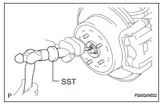
NOTICE: Loosen the staked part of the nut completely, otherwise the screw of the drive shaft may be damaged.
(b) While apply the brakes, remove the axle shaft nut.
5. REMOVE REAR DRIVE SHAFT ASSEMBLY LH
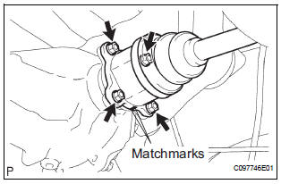
(a) Place matchmarks on the drive shaft and differential side gear shaft.
(b) Remove the 4 nuts and washers, and disconnect the drive shaft from the differential side gear shaft.
(c) Remove the drive shaft from the axle carrier.
6. SECURE REAR AXLE ASSEMBLY
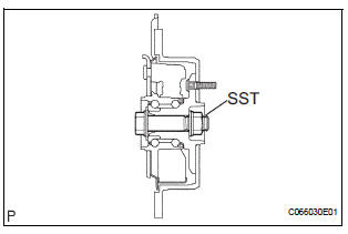
NOTICE:
- After disconnecting the drive shaft from the axle hub, work carefully so as not to damage the ABS speed sensor rotor serration on the drive shaft.
- The hub bearing could be damaged if it is
subjected to the vehicle weight, such as when
moving the vehicle with the drive shaft removed.
Therefore, if it is absolutely necessary to place the vehicle weight on the hub bearing, first support it with SST.
SST 09608-16042 (09608-02021, 09608-02041)
 Rear drive shaft (for 4wd)
COMPONENTS
...
 Disassembly
1. SEPARATE REAR DRIVE SHAFT INBOARD JOINT BOOT CLAMP
(a) Using a screwdriver, remove the 2 rear drive shaft
inboard joint boot clamps as shown in the
illustration.
2. SEPARATE REAR DRIVE SHAF ...
Other materials:
Reassembly
1. INSTALL MAGNETIC CLUTCH ASSEMBLY
(a) Install the magnetic clutch stator while aligning the
protrusion on the stator with the notch on the air
compressor assembly as shown in the illustration.
(b) Using a snap ring expander, install a new snap ring
with the chamfered side facing up.
...
Rear Occupant Classification Sensor LH Circuit
Malfunction
DTC B1782 Rear Occupant Classification Sensor LH Circuit
Malfunction
DESCRIPTION
The rear occupant classification sensor LH circuit consists of the occupant
classification ECU and the rear
occupant classification sensor LH.
DTC B1782 is recorded when a malfunction is detected in the rear oc ...
Installation
1. INSTALL NO. 1 REAR DIFFERENTIAL SUPPORT
(a) Install the No. 1 rear differential support to the rear
differential carrier assembly with the 2 bolts and 2
nuts.
Torque: 85 N*m (867 kgf*cm, 63 ft.*lbf)
HINT:
Hold the bolt and tighten the nut.
2. INSTALL REAR DIFFERENTIAL DYNAMIC DAMPER
...
