Toyota Sienna Service Manual: Removal and installation of engine intake parts
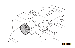
REMOVAL AND INSTALLATION OF ENGINE INTAKE PARTS
(a) If any metal particles enter inlet system parts, this may damage the engine.
(b) When removing and installing inlet system parts, cover the openings of the removed parts and engine openings. Use gummed tape or other suitable materials.
(c) When installing inlet system parts, check that no metal particles have entered the engine or the installed parts.
 Removal and installation of fuel control parts
(a) PLACE FOR REMOVING AND INSTALLING FUEL
SYSTEM PARTS
(1) Work in a location with good air ventilation that
does not have welders, grinders, drills, electric
motors, stoves, or any other ignitio ...
 Handling of hose clamps
HANDLING OF HOSE CLAMPS
(a) Before removing the hose, check the clamp position
so that it can be reinstalled in the same position.
(b) Replace any deformed or dented clamps with new
ones.
...
Other materials:
U151f automatic transaxle
SST
RECOMMENDED TOOLS
EQUIPMENT
LUBRICANT
SSM
...
Confirmation of transmitter id registration
(a) Make sure that the ignition switch is off.
(b) Connect the intelligent tester to DLC3.
(c) Turn the ignition switch to the ON position.
(d) Select "TIREPRESS" by following the prompts
displayed on the intelligent tester.
(e) Confirm that the data of tire pressure of all ti ...
Customize parameters
HINT:
The following item can be customized.
NOTICE:
After confirming whether the items requested by the
customer are applicable or not for customization,
perform the customize operation.
Be sure to record the current settings before
customizing.
When troubleshooting ...
