Toyota Sienna Service Manual: Reverse Signal Circuit
DESCRIPTION
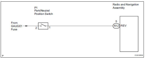
The radio and navigation assembly receives a reverse signal from the park/neutral position switch and information about the GPS antenna, and then adjusts vehicle position.
WIRING DIAGRAM
INSPECTION PROCEDURE
1 INSPECT RADIO AND NAVIGATION ASSEMBLY
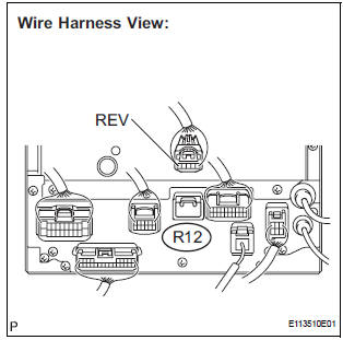
- Disconnect the radio and navigation assembly connector R12.
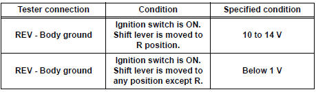
- Measure the voltage according to the value(s) in the table below.
Standard voltage
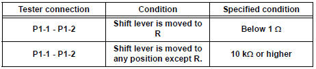
2 CHECK HARNESS AND CONNECTOR (RADIO AND NAVIGATION - PARK / NEUTRAL POSITION SWITCH)
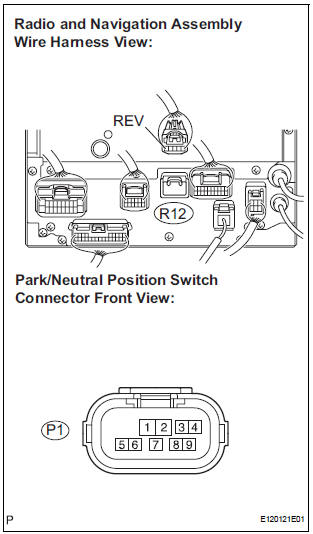
- Disconnect the radio and navigation assembly connector R12 and park/neutral position switch connector P1.
- Measure the resistance according to the value(s) in the table below.
Standard resistance
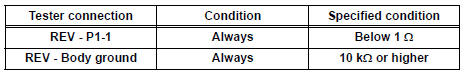
3 INSPECT PARK / NEUTRAL POSITION SWITCH
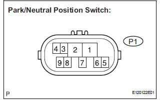
- Disconnect the park/neutral position switch connector P1.
- Measure the resistance according to the value(s) in the table below.
Standard resistance
REPAIR OR REPLACE HARNESS OR CONNECTOR
 AVC-LAN Circuit
DESCRIPTION
Each unit of the navigation system connected to the AVC-LAN (communication
bus) transfers the signal of
each switch by communication.
When a short to +B or short to ground occurs in ...
 Navigation Voice Circuit
DESCRIPTION
This circuit is used when the voice guidance in the navigation system is on.
WIRING DIAGRAM
INSPECTION PROCEDURE
1 CHECK HARNESS AND CONNECTOR (RADIO AND NAVIGATION ASSEMBLY - STER ...
Other materials:
Diagnosis system
1. CHECK DLC3
The vehicle's ECU uses ISO 15765-4 for
communication protocol. The terminal arrangement
of the DLC3 complies with SAE J1962 and matches
the ISO 15765-4 format.
NOTICE:
*: Before measuring the resistance, leave the
vehicle as is for at least 1 minute and do not
...
Speaking on the phone
The following screen is displayed when speaking on the phone.
To adjust the call volume
Select “-” or “+”. You can also adjust the volume using the steering
switches or the volume knob.
To prevent the other party from hearing your voice
Select “Mute”.
Inputting tones
When usin ...
Removal
1. DISCONNECT CABLE FROM NEGATIVE BATTERY
TERMINAL
CAUTION:
Wait for 90 seconds after disconnecting the cable to prevent the airbag working
2. REMOVE FRONT SEAT ASSEMBLY
HINT:
Refer to the instructions for removal of the front seat assembly (for
flat type).
Refer to the ins ...
