Toyota Sienna Service Manual: Reverse Signal Circuit
DESCRIPTION
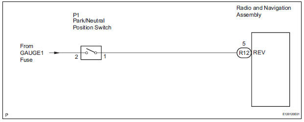
The radio and navigation assembly receives a reverse signal from the park/neutral position switch.
WIRING DIAGRAM
INSPECTION PROCEDURE
1 INSPECT RADIO AND NAVIGATION ASSEMBLY
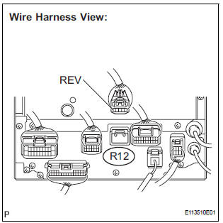
- Disconnect the radio and navigation assembly connector R12.
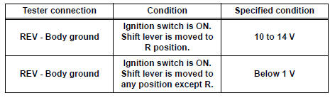
- Measure the voltage according to the value(s) in the table below.
Standard voltage
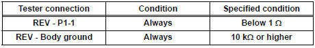
2 CHECK HARNESS AND CONNECTOR (RADIO AND NAVIGATION ASSEMBLY - PARK/ NEUTRAL POSITION SWITCH)
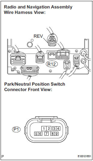
- Disconnect the radio and navigation assembly connector R12 and park/neutral position switch connector P1.
- Measure the resistance according to the value(s) in the table below.
Standard resistance
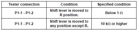
3 INSPECT PARK/NEUTRAL POSITION SWITCH ASSEMBLY
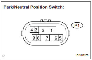
- Disconnect the park/neutral position switch connector P1.
- Measure the resistance according to the value(s) in the table below.
Standard resistance
REPAIR OR REPLACE HARNESS OR CONNECTOR
 Terminals of ECU
1. TELEVISION CAMERA ASSEMBLY
Disconnect the T10 camera connector
Measure the voltage and resistance of each
terminal of the wire harness side connector.
If the result is ...
 Display Signal Circuit between Radio and Navigation Assembly and
Television Camera Assembly
Display Signal Circuit between Radio and Navigation Assembly and
Television Camera Assembly
DESCRIPTION
This is the display signal circuit of the television camera assembly.
WIRING DIAGRAM
INSPECTION PROCEDURE
1 CHECK HARNESS AND CONNECTOR (RADIO AND NAVIGATION ASSEMBLY - TELEVISION ...
Other materials:
Installation
1. INSTALL OUTSIDE MOULDING
Using a heat light, heat the mounting surface of the
vehicle body between 40 to 60 C (104 to 140 F).
NOTICE:
Do not heat the body excessively.
Remove the tape from the vehicle body.
Wipe off the stains with cleaner.
Clean the outside moulding (if reusing t ...
Problem symptoms table
WINDOW DEFOGGER SYSTEM
Symptom
Suspected area
w/ Deicer: Front window deicer does not operate.
(indicator light ON)
FR DEF fuse
Front window deicer relay
Front window deicer wire
Wire harness
w/ deicer: Front window deicer ...
Reassembly
1. INSTALL STRAIGHT PIN
(a) Using a plastic hammer, tap in new straight pins to
the cylinder block.
Standard protrusion
2. INSTALL STUD BOLT
(a) Using E8 and E10 "TORX" sockets, install the stud
bolts.
Torque: 10 N*m (102 kgf*cm, 7 ft.*lbf) for bolt A
17 N*m (173 kgf*cm, ...
